
Datasheet


TL16C554A, TL16C554AI
ASYNCHRONOUS-COMMUNICATIONS ELEMENT
SLLS509E − AUGUST 2001 − REVISED JUNE 2010
17
POST OFFICE BOX 655303 • DALLAS, TEXAS 75265
PARAMETER MEASUREMENT INFORMATION
Active
(see Note A)
Stop
t
d9
(see Note B)
t
pd5
IOR
(RD RBR)
SIN
(first byte that reaches
the trigger level)
Sample
Clock
RXRDY
50%
50%
50%
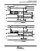
NOTES: A. This is the reading of the last byte in the FIFO.
B. If FCR0 = 1, t
d9
= 3 RCLK cycles. For a trigger change level interrupt, t
d9
= 8 RCLK.
Figure 13. Receiver Ready Mode 1 Timing Waveforms
t
pd6
t
pd6
t
pd7
t
pd7
t
pd8
t
pd9
IOW
(WR MCR)
IOR
(RD MSR)
RTSx, DTRx
CTSx
, DSRx,
DCDx
RIx
INTx
50%
50%
50%
50%
50%
50%
50%50% 50%
50%
50%
50%
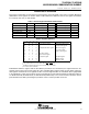
Figure 14. Modem Control Timing Waveforms