
Datasheet


Receiver
Buffer
Register
Divisor
Latch (LS)
Divisor
Latch (MS)
Baud
Generator
Receiver
FIFO
Line
Status
Register
Transmitter
Holding
Register
Modem
Control
Register
Modem
Status
Register
Line
Control
Register
Transmitter
FIFO
Interrupt
Enable
Register
Interrupt
Identification
Register
FIFO
Control
Register
Select
and
Control
Logic
Interrupt
Control
Logic
S
e
l
e
c
t
Data
Bus
Buffer
BAUDOUT
SIN
RCLK
SOUT
CTS
DTR
DSR
DCD
RI
OUT1
OUT2
INTRPT
38
33
39
40
41
34
31
30
8
5
7
12
9
A0
28
D(7- 0)
4-2
47-43
Internal
Data Bus
27
26
10
11
24
35
19
20
16
17
22
23
14
15
29
A1
A2
CS0
CS1
CS2
ADS
MR
RD1
RD2
WR1
WR2
DDIS
TXRDY
XIN
XOUT
RXRDY
S
e
l
e
c
t
Receiver
Shift
Register
Receiver
Timing and
Control
Transmitter
Timing and
Control
Transmitter
Shift
Register
Modem
Control
Logic
8
42
18
V
CC
V
SS
Power
Supply
RTS
32
Autoflow Control
(AFE)
8
8
8
8
8
8
8
TL16C550D , , TL16C550DI
www.ti.com
.................................................................................................................................................. SLLS597E – APRIL 2004 – REVISED DECEMBER 2008
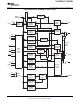
FUNCTIONAL BLOCK DIAGRAM (For PT and PFB Packages)
Copyright © 2004 – 2008, Texas Instruments Incorporated Submit Documentation Feedback 5
Product Folder Link(s): TL16C550D TL16C550DI