
Datasheet


SLLS037C − MARCH 1988 − REVISED JANUARY 2006
7
POST OFFICE BOX 655303 • DALLAS, TEXAS 75265
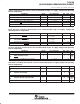
system switching characteristics over recommended ranges of supply voltage and operating
free-air temperature
PARAMETER FIGURE TEST CONDITIONS MIN MAX UNIT
t
w1
Pulse duration, clock high 1 f = 9 MHz maximum 50 ns
t
w2
Pulse duration, clock low 1 f = 9 MHz maximum 50 ns
t
d3
Delay time, select to CS output 2,3
†
C
L
= 100 pF 70 ns
t
d10
Delay time, RD1↓ or RD2↑ to data valid 3 C
L
= 100 pF 60 ns
t
d11
Delay time, RD1↑ or RD2↓ to floating data 3 C
L
= 100 pF 0 60 ns
t
dis(R)
Disable time, RD1↓↑ or RD2↑↓ to DDIS↑↓ 3 C
L
= 100 pF 60 ns
†
Only applies when ADS
is low.
baud generator switching characteristics over recommended ranges of supply voltage and
operating free-air temperature
PARAMETER FIGURE TEST CONDITIONS MIN MAX UNIT
t
w3
Pulse duration, BAUDOUT low
1
f = 6.25 MHz, CLK
÷
1,
80
ns
t
w3
Pulse duration, BAUDOUT low
1
f = 6.25 MHz, CLK ÷ 1,
C
L
= 100 pF
80 ns
t
w4
Pulse duration, BAUDOUT high
1
f = 6.25 MHz, CLK
÷
1,
80
ns
t
w4
Pulse duration, BAUDOUT high
1
f = 6.25 MHz, CLK ÷
1,
C
L
= 100 pF
80 ns
t
d1
Delay time, XIN↑ to BAUDOUT↑ 1 C
L
= 100 pF 125 ns
t
d2
Delay time, XIN↑↓ to BAUDOUT↓ 1 C
L
= 100 pF 125 ns
receiver switching characteristics over recommended ranges of supply voltage and operating
free-air temperature
PARAMETER FIGURE TEST CONDITIONS MIN MAX UNIT
t
d12
Delay time, RCLK to sample clock 4 100 ns
t
d13
Delay time, stop to set RCV error interrupt or read
RDR to LSI interrupt or stop to
4
1
1
RCLK
t
d13
RDR to LSI interrupt or stop to
RXRDY↓
4 1 1
RCLK
cycles
t
d14
Delay time, read RBR/LSR to reset interrupt 4 C
L
= 100 pF 140 ns
transmitter switching characteristics over recommended ranges of supply voltage and operating
free-air temperature
PARAMETER FIGURE TEST CONDITIONS MIN MAX UNIT
t
d15
Delay time, INTRPT to transmit start
5
8
24
baudout
t
d15
Delay time, INTRPT to transmit start 5 8 24
baudout
cycles
t
d16
Delay time, start to interrupt
5
8
8
baudout
t
d16
Delay time, start to interrupt 5 8 8
baudout
cycles
t
d17
Delay time, WR THR to reset interrupt 5 C
L
= 100 pF 140 ns
t
d18
Delay time, initial write to interrupt (THRE)
5
16
32
baudout
t
d18
Delay time, initial write to interrupt (THRE) 5 16 32
baudout
cycles
t
d19
Delay time, read IIR to reset interrupt (THRE) 5 C
L
= 100 pF 140 ns