
Datasheet


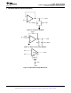


IN+
50 Ω
100 Ω
C1
V
CC+
OUT V
CC−
OFFSET N1
TL061 Only
OFFSET N2
IN−
C1 = 10 pF on TL061, TL062, and TL064
Component values shown are nominal.
TL061
,
TL061A
,
TL061B
TL062
,
TL062A
,
TL062B
,
TL064
,
TL064A
,
TL064B
SLOS078L –NOVEMBER 1978–REVISED MAY 2015
www.ti.com
8 Detailed Description
8.1 Overview
The JFET-input operational amplifiers of the TL06x series are designed as low-power versions of the TL08x
series amplifiers. They feature high input impedance, wide bandwidth, high slew rate, and low input offset and
input bias currents. The TL06x series features the same terminal assignments as the TL07x and TL08x series.
Each of these JFET-input operational amplifiers incorporates well-matched, high-voltage JFET and bipolar
transistors in an integrated circuit.
The C-suffix devices are characterized for operation from 0°C to 70°C. The I-suffix devices are characterized for
operation from −40°C to 85°C, and the M-suffix devices are characterized for operation over the full military
temperature range of −55°C to 125°C.
8.2 Functional Block Diagram
8.3 Feature Description
8.3.1 Common-Mode Rejection Ratio
The common-mode rejection ratio (CMRR) of an amplifier is a measure of how well the device rejects unwanted
input signals common to both input leads. It is found by taking the ratio of the change in input offset voltage to
the change in the input voltage and converting to decibels. Ideally the CMRR is infinite, but in practice, amplifiers
are designed to have it as high as possible. The CMRR of this device is 86 dB.
8.3.2 Slew Rate
The slew rate is the rate at which an operational amplifier can change its output when there is a change on the
input. These devices have a 3.5-V/μs slew rate.
14 Submit Documentation Feedback Copyright © 1978–2015, Texas Instruments Incorporated
Product Folder Links: TL061 TL061A TL061B TL062 TL062A TL062B TL064 TL064A TL064B