
Datasheet


TL05x, TL05xA
ENHANCED-JFET LOW-OFFSET
OPERATIONAL AMPLIFIERS
SLOS178A – FEBRUARY 1997 - REVISED FEBRUARY 2003
14
POST OFFICE BOX 655303 • DALLAS, TEXAS 75265
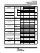
TL054C and TL054AC operating characteristics at specified free-air temperature
†
TL054C, TL054C
PARAMETER TEST CONDITIONS
T
A
†
V
CC±
= ±5 V V
CC±
= ±15 V
UNIT
MIN TYP MAX MIN TYP MAX
SR+
Positive slew rate
25°C 15.4 10 17.8
SR
+
at unity gain
0°C 15.7 8 17.9
R
L
= 2 kΩ,C
L
= 100 pF,
70°C 14.4 8 17.5
V/µs
SR
Ne
g
ative slew rate at
L L
See Figure 1 and Note 7
25°C 13.9 10 15.9
V/
µ
s
SR
–
g
unity gain
‡
0°C 14.3 8 16.1
70°C 13.3 8 15.5
25°C 55 56
t
r
Rise time 0°C 54 55
70°C 63 63
ns
V
I(PP)
= ±10 mV,
R2kΩ
25°C 55 57
ns
t
f
Fall time
R
L
=
2
kΩ
,
C
L
= 100
p
F
0°C 54 56
C
L
=
100
F
,
See Fi
g
ures 1 and 2
70°C 62 64
See
Figures
1
and
2
25°C 24% 19%
Overshoot factor 0°C 24% 19%
%
70°C 24% 19
V
E
q
uivalent input noise
f = 10 Hz 25°C 75 75
nV/√Hz
V
n
q
voltage
§
R
S
= 20 Ω,
f = 1 kHz 25°C 21 21 45
nV/√Hz
V
N(PP)
Peak-to-peak equivalent
input noise voltage
See Figure 3
f = 10 Hz to
10 kHz
25°C 4 4 µV
I
n
Equivalent input
noise current
f = 1 kHz 25°C 0.01 0.01
pA/√Hz
THD
Total harmonic
distortion
¶
R
S
= 1 kΩ,
f = 1 kHz
R
L
= 2 kΩ,
25°C 0.003 0.003 %
V10mV R 2kΩ
25°C 2.7 2.7
B
1
Unity-gain bandwidth
V
I
=
10
m
V
,
R
L
=
2
kΩ
,
C
L
=25
p
F See Figure 4
0°C 3 3 MHz
C
L
=
25
F
,
See
Figure
4
70°C 2.4 2.4
Phase margin at
V
I
=10mV R
L
=2kΩ
25°C 61 64
φ
m
Phase
margin
at
unity gain
V
I
=
10
mV
,
R
L
=
2
kΩ
,
C
L
=
25
p
F See Figure 4
0°C 60 64 deg
unity
gain
C
L
=
25
F
,
See
Figure
4
70°C 61 63
†
Full range is 0°C to 70°C.
‡
For V
CC±
= ±5 V, V
I(PP)
= ±1 V; for V
CC±
= ±15 V, V
I(PP)
= ±5 V.
§
This parameter is tested on a sample basis. For other test requirements, please contact the factory. This statement has no bearing on testing
or nontesting of other parameters.
¶
For V
CC±
= ±5 V, V
O(RMS
) = 1 V; for V
CC±
= ±15 V, V
O(RMS)
= 6 V.