
Datasheet


SLOS388B − OCTOBER 2001 − REVISED JUNE 2002
17
www.ti.com
APPLICATION INFORMATION
alternative transimpedance configurations
Other transimpedance configurations are possible. Three possibilities are shown below.
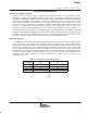
The first configuration is a slight modification of the basic transimpedance circuit. By splitting the feedback
resistor, the feedback capacitor value becomes more manageable and easier to control. This type of
compensation scheme is useful when the feedback capacitor required in the basic configuration becomes so
small that the parasitic effects of the board and components begin to dominate the total feedback capacitance.
By reducing the resistance across the capacitor, the capacitor value can be increased. This mitigates the
dominance of the parasitic effects.
_
+
C
F
R
F2
R
L
R
F1
−V
Bias
λ
NOTE: Splitting the feedback resistor enables use of a larger, more manageable feedback
capacitor.
Figure 33. Alternative Transimpedance Configuration #1
The second configuration uses a resistive T-network to achieve very high transimpedance gains using relatively
small resistor values. This topology can be very useful when the desired transimpedance gain exceeds the
value of available resistors. The transimpedance gain is given by equation 3.
R
EQ
+ R
F1
ǒ
1 )
R
F2
R
F3
Ǔ
_
+
C
F
R
F2
R
L
R
F1
−V
Bias
R
F3
λ
NOTE: A resistive T-network enables high transimpedance gain with reasonable resistor values.
Figure 34. Alternative Transimpedance Configuration #2
(3)