
Datasheet


POWER DISSIPATION AND THERMAL
2
1.5
1
0
−40 −20 0 20
− Maximum Power Dissipation − W
2.5
3
3.5
40 60 80
T
A
− Ambient Temperature − °C
P
D
8-Pin DGN Package
θ
JA
= 170°C/W for 8-Pin SOIC (D)
θ
JA
= 58.4°C/W for 8-Pin MSOP (DGN)
Τ
J
= 150°C, No Airflow
0.5
8-Pin D Package
P
Dmax
=
T
max A
T-
q
JA
(28)
DRIVING CAPACITIVE LOADS
V
S
R
S
R
G
R
F
R
F
+
R
T
R
ISO
C
L
R
G
R =10 25- W
ISO
V
S
-V
S
R
ISO
+
-
-
THS4504
THS4505
SLOS363D – AUGUST 2002 – REVISED MAY 2008 .........................................................................................................................................................
www.ti.com
CONSIDERATIONS
The THS4500 family of devices does not incorporate
automatic thermal shutoff protection, so the designer
must take care to ensure that the design does not
violate the absolute maximum junction temperature of
the device. Failure may result if the absolute
maximum junction temperature of +150 ° C is
exceeded. For best performance, design for a
maximum junction temperature of +125 ° C. Between
+125 ° C and +150 ° C, damage does not occur, but the
performance of the amplifier begins to degrade.
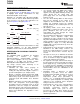
The thermal characteristics of the device are dictated
by the package and the PC board. Maximum power
dissipation for a given package can be calculated
using the following formula.
Figure 91. Maximum Power Dissipation vs
Ambient Temperature
Where:
When determining whether or not the device satisfies
P
Dmax
is the maximum power dissipation in the
the maximum power dissipation requirement, it is
amplifier (W).
important to not only consider quiescent power
T
MAX
is the absolute maximum junction
dissipation, but also dynamic power dissipation. Often
temperature ( ° C).
times, this is difficult to quantify because the signal
pattern is inconsistent, but an estimate of the RMS
T
A
is the ambient temperature ( ° C).
power dissipation can provide visibility into a possible
θ
JA
= θ
JC
+ θ
CA
problem.
θ
JC
is the thermal coefficient from the silicon
junctions to the case ( ° C/W).
θ
CA
is the thermal coefficient from the case to
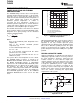
High-speed amplifiers are typically not well-suited for
ambient air ( ° C/w).
driving large capacitive loads. If necessary, however,
For systems where heat dissipation is more critical,
the load capacitance should be isolated by two
the THS4500 family of devices is offered in an
isolation resistors in series with the output. The
MSOP-8 with PowerPAD. The thermal coefficient for
requisite isolation resistor size depends on the value
the MSOP PowerPAD package is substantially
of the capacitance, but 10 Ω to 25 Ω is a good place
improved over the traditional SOIC. Maximum power
to begin the optimization process. Larger isolation
dissipation levels are depicted in the graph for the
resistors decrease the amount of peaking in the
two packages. The data for the DGN package
frequency response induced by the capacitive load,
assumes a board layout that follows the PowerPAD
but this comes at the expense of larger voltage drop
layout guidelines referenced above and detailed in
across the resistors, increasing the output swing
the PowerPAD application notes in the Additional
requirements of the system.
Reference Materialsection at the end of the data
sheet.
Figure 92. Use of Isolation Resistors with a
Capacitive Load
30 Submit Documentation Feedback Copyright © 2002 – 2008, Texas Instruments Incorporated
Product Folder Link(s): THS4504 THS4505