
Datasheet


THS4221, THS4225
THS4222, THS4226
SLOS399G − AUGUST 2002 − REVISED JANUARY 2004
www.ti.com
17
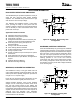
APPLICATION CIRCUITS
Driving an Analog-to-Digital Converter With the
THS4222
The THS4222 can be used to drive high-performance
analog-to-digital converters. Two example circuits are
presented below.
The first circuit uses a wideband transformer to convert a
single-ended input signal into a differential signal. The
differential signal is then amplified and filtered by two
THS4222 amplifiers. This circuit provides low
intermodulation distortion, suppressed even-order
distortion, 14 dB of voltage gain, a 50-Ω input impedance,
and a single-pole filter at 25 MHz. For applications without
signal content at dc, this method of driving ADCs can be
very useful. Where dc information content is required, the
THS4500 family of fully differential amplifiers may be
applicable.
_
+
THS4222
50 Ω
Source
1.3 kΩ
_
+
THS4222
−5 V
649 Ω
4.7 pF
1.3 kΩ
649 Ω 24.9 Ω
4.7 pF
12-Bit, 53 Msps
ADS807
(1:4 Ω)
1:2
5 V
24.9 Ω
237 Ω
Figure 32. A Linear, Low Noise, High Gain ADC
Preamplifier
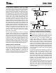
The second circuit depicts single-ended ADC drive. While
not recommended for optimum performance using
converters with differential inputs, satisfactory
performance can sometimes be achieved with
single-ended input drive. An example circuit is shown here
for reference.
_
+
THS4222
1.3 kΩ
ADS807
12-Bit,
53 Msps
R
f
+5 V
1.3 kΩ
49.9 Ω
V
I
R
g
−5 V
50 Ω
Source
R
ISO
0.1 µF
16.5 Ω
68 pf
0.1 µF
IN
IN
CM
1.82 kΩ
R
T
NOTE
:
For best performance, high-speed ADCs should be driven
differentially. See the THS4500 family of devices for more
information.
Figure 33. Driving an ADC With a
Single-Ended Input
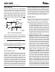
Active Filtering With the THS4222
High-frequency active filtering with the THS4222 is
achievable due to the amplifier’s high slew rate, wide
bandwidth, and voltage feedback architecture. Several
options are available for high-pass, low-pass, bandpass,
and bandstop filters of varying orders. A simple two-pole
low pass filter is presented here as an example, with two
poles at about 25 MHz.
_
+
THS4222
49.9 Ω
50 Ω Source
1.3 kΩ
4.7 pF
5 V
−5 V
120 pF
V
O
1.3 kΩ
52.3 Ω
V
I
Figure 34. A Two-Pole Active Filter With Two
Poles at about 25 MHz