
Datasheet


V
CC
PD
V
CC−
To Internal Bias
Circuitry Control
50 kΩ
200
1200
2200
100 k 1 M 10 M 100 M 1 G
Output Impedance −
f − Frequency − Hz
Ω
V
CC
= ±5 V
G = 1
R
f
= 1 kΩ
PD
= V
CC−
THS4130
THS4131
www.ti.com
SLOS318H –MAY 2000– REVISED MAY 2011
POWER-DOWN MODE
The power-down mode is used when power saving is required. The power-down terminal (PD) found on the
THS413x is an active low terminal. If it is left as a no-connect terminal, the device always stays on due to an
internal 50 kΩ resistor to V
CC
. The threshold voltage for this terminal is approximately 1.4 V above V
CC–
. This
means that if the PD terminal is 1.4 V above V
CC–
, the device is active. If the PD terminal is less than 1.4 V
above V
CC–
, the device is off. For example, if V
CC–
= –5 V, then the device is on when PD reaches –3.6 V, (–5 V
+ 1.4 V = –3.6 V). By the same calculation, the device is off below –3.6 V. It is recommended to pull the terminal
to V
CC–
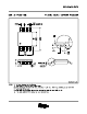
in order to turn the device off. Figure 41 shows the simplified version of the power-down circuit. While in
the power-down state, the amplifier goes into a high-impedance state. The amplifier output impedance is typically
greater than 1 MΩ in the power-down state.
Figure 41. Simplified Power-Down Circuit
Due to the similarity of the standard inverting amplifier configuration, the output impedance appears to be very
low while in the power-down state. This is because the feedback resistor (R
f
) and the gain resistor (R
(g)
) are still
connected to the circuit. Therefore, a current path is allowed between the input of the amplifier and the output of
the amplifier. An example of the closed loop output impedance is shown in Figure 42.
Figure 42. Output Impedance (In Power-Down) vs Frequency
Copyright © 2000–2011, Texas Instruments Incorporated 21