
Datasheet


P
D
+
ǒ
T
MAX
–T
A
q
JA
Ǔ
Where:
P
D
= Maximum power dissipation of THS403x IC (watts)
T
MAX
= Absolute maximum operating junction temperature (125°C)
T
A
= Free-ambient air temperature (°C)
θ
JA
= θ
JC
+ θ
CA
θ
JC
= Thermal coefficient from junction to case
θ
CA
= Thermal coefficient from case to ambient air (°C/W)
MAXIMUMPOWERDISSIPATION
AMBIENTTEMPERATURE
vs
0
0.5
1
1.5
2
2.5
3
-40 -20 0 20 40 60 80 100
T
A
-Free AirTemperature-°C
MaximumPowerDissipation-W
DGNPackage
=58.4ºC/W2oz.
TraceandCopperPad
WithSolder
q
JA
T =130ºC
J
DGNPackage
=158.4ºC/W2oz.
TraceandCopperPad
WithoutSolder
q
JA
SOICPackage
High-KTestPCB
=98ºC/Wq
JA
SOICPackage
High-KTestPCB
=166.7ºC/Wq
JA
THS4031
THS4032
SLOS224G –JULY 1999–REVISED MARCH 2010
www.ti.com
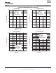
The actual thermal performance achieved with the THS403xDGN in its PowerPAD™ package depends on the
application. In the example above, if the size of the internal ground plane is approximately 3 inches × 3 inches
(7,62 cm × 7,62 cm), then the expected thermal coefficient, q
JA
, is about 58.4°C/W. For comparison, the
non-PowerPAD™ version of the THS403x IC (SOIC) is shown. For a given q
JA
, the maximum power dissipation
is shown in Figure 62 and is calculated by the following formula:
(3)
Results are with no air flow and PCB size = 3”× 3” (7,62 cm x 7,62 cm)
Figure 62. Maximum Power Dissipation vs Free-Air Temperature
More complete details of the PowerPAD installation process and thermal management techniques can be found
in the Texas Instruments technical brief, PowerPAD™ Thermally-Enhanced Package (SLMA002). This document
can be found at the TI web site (www.ti.com) by searching on the key word PowerPAD. The document can also
be ordered through your local TI sales office. Refer to literature number SLMA002 when ordering.
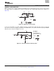
The next thing to be considered is package constraints. The two sources of heat within an amplifier are quiescent
power and output power. The designer should never forget about the quiescent heat generated within the device,
especially multiamplifier devices. Because these devices have linear output stages (Class A-B), most of the heat
dissipation is at low output voltages with high output currents. Figure 63 to Figure 66 shows this effect, along with
the quiescent heat, with an ambient air temperature of 50°C. When using V
CC
= ±5 V, heat is generally not a
problem, even with SOIC packages. But, when using V
CC
= ±15 V, the SOIC package is severely limited in the
amount of heat it can dissipate. The other key factor when looking at these graphs is how the devices are
mounted on the PCB. The PowerPAD™ devices are extremely useful for heat dissipation. But, the device should
30 Submit Documentation Feedback Copyright © 1999–2010, Texas Instruments Incorporated
Product Folder Link(s): THS4031 THS4032