
Datasheet


SLAS284A – AUGUST 2000 – REVISED DECEMBER 2002
www.ti.com
24
Write Timing (using WR, WR-controlled)
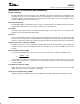
Figure 33 shows the write-timing behavior when the WR
(R/W) input is programmed as a write input WR only. The
input RD acts as the read input in this configuration. This timing is called WR-controlled because WR is the last
external signal of CS0, CS1, and WR which becomes valid.
90%90%
10%
t
su
t
h
D(0–9)
DATA_AV
10%
t
w(WR)
t
su(CS)
t
h(CS)
CS0
CS1
WR
RD
Figure 33. Write Timing Diagram Using WR (WR-controlled)
Write Timing Parameter Using WR (WR-controlled)
PARAMETER MIN TYP MAX UNIT
t
su(CS)
Setup time, CS stable to last WR valid 0 ns
t
su
Setup time, data valid to first WR invalid 5 ns
t
h
Hold time, WR invalid to data invalid 2 ns
t
h(CS)
Hold time, WR invalid to CS change 5 ns
t
w(WR)
Pulse duration, WR active 10 ns