
Information


TFP401
TFP401A
SLDS120E –MARCH 2000–REVISED JULY 2013
www.ti.com
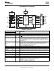
AC ELECTRICAL CHARACTERISTICS (continued)
over recommended operating free-air temperature range (unless otherwise noted)
PARAMETER TEST CONDITIONS MIN TYP MAX UNIT
1 pixel/clock, PIXS = low,
2.1
OCK_INV = high
Setup time, data and control signal to rising edge of 2 pixel/clock, PIXS = high,
t
su2
4 ns
ODCK STAG = high, OCK_INV = high
2 pixel and STAG, PIXS = high,
1.5
STAG = low, OCK_INV = high
1 pixel/clock, PIXS = low,
0.5
OCK_INV = high
Hold time, data and control signal to rising edge of 2 pixel and STAG, PIXS = high,
t
h2
2.4 ns
ODCK STAG = low, OCK_INV = high
2 pixel/clock, PIXS = high,
2.1
STAG = high, OCK_INV = high
PIX = low (1-PIX/CLK) 25 165
f
ODCK
ODCK frequency MHz
PIX = high (2-PIX/CLK) 12.5 82.5
ODCK duty-cycle 40% 50% 60%
t
pd(PDL)
Propagation delay time from PD low to Hi-Z outputs 9 ns
Propagation delay time from PDO low to Hi-Z
t
pd(PDOL)
9 ns
outputs
t
t(HSC)
Transition time between DE transition to SCDT
1e6 t
pix
low
(8)
Transition time between DE transition to SCDT
t
t(FSC)
1600 t
pix
high
(8)
Delay time, ODCK latching edge to QE[23:0] data
t
d(st)
STAG = low, PIXS = high 0.25 t
pix
output
(8) Link active or inactive is determined by amount of time detected between DE transitions. SCDT indicates link activity.
8 Submit Documentation Feedback Copyright © 2000–2013, Texas Instruments Incorporated
Product Folder Links: TFP401 TFP401A