
Datasheet


TFP401A-EP
www.ti.com
SLDS160A –MARCH 2009– REVISED JULY 2011
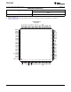
TERMINAL FUNCTIONS (continued)
TERMINAL
I/O DESCRIPTION
NAME NO.
Channel-0 negative receiver input - Negative side of channel-0. TMDS low voltage signal
Rx0- 91 AI
differential input pair.
Channel-1 positive receiver input - Positive side of channel-1 TMDS low voltage signal
Rx1+ 85 AI differential input pair.
Channel-1 receives green pixel data in active display and CTL1 control signals in blank.
Channel-1 negative receiver input - Negative side of channel-1 TMDS low voltage signal
Rx1- 86 AI
differential input pair.
Channel-2 positive receiver input - Positive side of channel-2 TMDS low voltage signal
Rx2+ 80 AI differential input pair.
Channel-2 receives red pixel data in active display and CTL2, CTL3 control signals in blank.
Channel-2 negative receiver input - Negative side of channel-2 TMDS low voltage signal
Rx2- 81 AI
differential input pair.
Sync detect - Output to signal when the link is active or inactive. The link is considered to be
active when DE is actively switching. The TFP401A monitors the state DE to determine link
activity. SCDT can be tied externally to PDO to power down the output drivers when the link
SCDT 8 DO
is inactive.
High: Active link
Low: Inactive link
Output drive strength select - Selects output drive strength for high or low current drive. (See
dc specifications for IOH and IOL vs ST state).
ST 3 DI
High : High drive strength
Low : Low drive strength
Staggered pixel select - An active low signal used in the 2-pixel/clock pixel mode
(PIXS = high). Time staggers the even and odd pixel outputs to reduce ground bounce.
STAG 7 DI Normal operation outputs the odd and even pixels simultaneously.
High : Normal simultaneous even/odd pixel output
Low: Time staggered even/odd pixel output
VSYNC 47 DO Vertical sync output
ABSOLUTE MAXIMUM RATINGS
(1)
over operating free-air temperature range (unless otherwise noted)
MIN MAX UNIT
DV
DD
, AV
DD
, OV
DD
, PV
DD
Supply voltage range -0.3 4 V
V
I
Input voltage range, logic/analog signals -0.3 4 V
Operating ambient temperature range -55 125 °C
T
stg
Storage temperature range
(2)
–65 150 °C
T
c
Case temperature for 10 seconds 260 °C
Lead temperature 1,6 mm (1/16 inch) from case for 10 seconds 260 °C
Soldered
(3)
4.3
Package power dissipation/ PowerPAD™ W
Not soldered
(4)
2.7
KV
Human
ESD protection, all pins 25
Body
Model
JEDEC latchup (EIA/JESD78) 100 mA
(1) Stresses beyond those listed under "absolute maximum ratings" may cause permanent damage to the device. These are stress ratings
only, and functional operation of the device at these or any other conditions beyond those indicated under "recommended operating
conditions" is not implied. Exposure to absolute-maximum-rated conditions for extended periods may affect device reliability.
(2) Long-term high–temperature storage and/or extended use at maximum recommended operating conditions may result in a reduction of
overall device life. See http://www.ti.com/ep_quality for additional information on enhanced plastic packaging
(3) Specified with PowerPAD™ bond pad on the backside of the package soldered to a 2 oz. Cu plate PCB thermal plane. Specified at
maximum allowed operating temperature, 70°C.
(4) PowerPAD™ bond pad on the backside of the package is not soldered to a thermal plane. Specified at maximum allowed operating
temperature, 70°C.
Copyright © 2009–2011, Texas Instruments Incorporated 5