
Datasheet


TFP401A-EP
SLDS160A –MARCH 2009– REVISED JULY 2011
www.ti.com
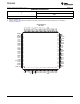
TERMINAL FUNCTIONS (continued)
TERMINAL
I/O DESCRIPTION
NAME NO.
Power down - An active low signal that controls the TFP401A power-down state. During
power down all output buffers are switched to a high impedance state. All analog circuits are
powered down and all inputs are disabled, except for PD.
PD 2 DI
If PD is left unconnected an internal pullup defaults the TFP401A to normal operation.
High : Normal operation
Low: Power down
Output drive power down - An active low signal that controls the power-down state of the
output drivers. During output drive power down, the output drivers (except SCDT and CTL1)
are driven to a high impedance state. When PDO is left unconnected, an internal pullup
PDO 9 DI
defaults the TFP401A to normal operation.
High : Normal operation/output drivers on
Low: Output drive power down.
PGND 98 GND PLL GND - Ground reference and current return for internal PLL
Pixel select - Selects between one or two pixels per clock output modes. During the
2-pixel/clock mode, both even pixels, QE[23:0], and odd pixels, QO[23:0], are output in
tandem on a given clock cycle. During 1-pixel/clock, even and odd pixels are output
sequentially, one at a time, with the even pixel first, on the even pixel bus, QE[23:0]. (The
PIXS 4 DI
first pixel per line is pixel-0, the even pixel. The second pixel per line is pixel-1, the odd
pixel).
High : 2-pixel/clock
Low: 1-pixel/clock
PV
DD
97 V
DD
PLL V
DD
- Power supply for internal PLL
Even green pixel output - Output for even and odd green pixels when in 1-pixel/clock mode.
Output for even only green pixel when in 2-pixel/clock mode. Output data is synchronized to
QE[8:15] 20-27 DO the output data clock, ODCK.
LSB: QE8/pin 20
MSB: QE15/pin 27
Even red pixel output - Output for even and odd red pixels when in 1-pixel/clock mode.
Output for even only red pixel when in 2-pixel/clock mode. Output data is synchronized to the
QE[16:23] 30-37 DO output data clock, ODCK.
LSB: QE16/pin 30
MSB: QE23/pin 37
Odd blue pixel output - Output for odd only blue pixel when in 2-pixel/clock mode. Not used,
and held low, when in 1-pixel/clock mode. Output data is synchronized to the output data
QO[0:7] 49-56 DO clock, ODCK.
LSB: QO0/pin 49
MSB: QO7/pin 56
Odd green pixel output - Output for odd only green pixel when in 2-pixel/clock mode. Not
used, and held low, when in 1-pixel/clock mode. Output data is synchronized to the output
QO[8:15] 59-66 DO data clock, ODCK.
LSB: QO8/pin 59
MSB: QO15/pin 66
Odd red pixel output - Output for odd only red pixel when in 2-pixel/clock mode. Not used,
and held low, when in 1-pixel/clock mode. Output data is synchronized to the output data
QO[16:23] 69-75, 77 DO clock, ODCK.
LSB: QO16/pin 69
MSB: QO23/pin 77
Even blue pixel output - Output for even and odd blue pixels when in 1-pixel/clock mode.
Output for even only blue pixel when in 2-pixel per clock mode. Output data is synchronized
QE[0:7] 10-17 DO to the output data clock, ODCK.
LSB: QE0/pin 10
MSB: QE7/pin 17
Clock positive receiver input - Positive side of reference clock. TMDS low voltage signal
RxC+ 93 AI
differential input pair.
Clock negative receiver input - Negative side of reference clock. TMDS low voltage signal
RxC- 94 AI
differential input pair.
Channel-0 positive receiver input - Positive side of channel-0. TMDS low voltage signal
differential input pair.
Rx0+ 90 AI
Channel-0 receives blue pixel data in active display and HSYNC, VSYNC control signals in
blank.
4 Copyright © 2009–2011, Texas Instruments Incorporated