
Datasheet


TAS5548
www.ti.com
SLES270 –NOVEMBER 2012
5.3 Device Configuration Controls
The TAS5548 provides a number of system configuration controls that can be set at initialization and set
following a reset.
• Channel configuration
• Headphone configuration
• Audio system configurations
• Recovery from clock error
• Power-supply volume-control enable
• Volume and mute update rate
• Modulation index limit
• Master-clock and data-rate controls
• Bank controls
5.3.1 Channel Configuration
These registers control the TAS5548 response to back end errors.
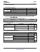
Table 5-5. Description of the Channel Configuration Registers (0x05 to 0x0C)
BIT DESCRIPTION
D7 Enable/disable error recovery sequence. In case the BKND_ERR pin is pulled low, this register determines if this channel is to
follow the error recovery sequence or to continue with no interruption.
D6 Determines if the power stage needs the TAS5548 VALID pin to go low to reset the power stage. Some power stages can be
reset by a combination of PWM signals. For these devices, it is recommended to set this bit low, because the VALID pin is
shared for power stages. This provides better control of each power stage.
D5 Determines if the power stage needs the TAS5548 VALID pin to go low to mute the power stage. Some power stages can be
muted by a combination of PWM signals. For these devices, it is recommended to set this bit low, because the VALID pin is
shared for power stages. This provides better control of each power stage.
D4 Inverts the PWM output. Inverting the PWM output can be an advantage if the power stage input pin is opposite the TAS5548
PWM pinout. This makes routing on the PCB easier. To keep the phase of the output, the speaker terminals must also be
inverted.
D3 When using the TI Power Stage this bit must be set. (Specifically for the TAS5182)
D2 Can be used to handle click and pop for some applications.
D1 This bit is normally used together with D2. For some power stages, both PWM signals must be high to get the desired operation
of both speaker outputs to be low. This bit sets the PWM outputs high-high during mute.
D0 Not used
5.3.2 Headphone Configuration Registers
The headphone configuration controls are identical to the speaker configuration controls. The headphone
configuration control settings are used in place of the speaker configuration control settings for channels 1
and 2 when the headphones are selected. However, only one configuration setting for headphones is
used, and it is the default setting, i.e. in headphone mode 0x05 and 0x06 settings are fixed in default.
5.3.3 Audio System Configurations
The TAS5548 can be configured to comply with various audio systems: 5.1-channel system, 6-channel
system, 7.1-channel system, and 8-channel system.
The audio system configuration is set in the general control register (0xE0). Bits D31–D4 must be zero
and D0 is do not care.
D3 Must always be 0 (default). Note that subwoofer cannot be used as lineout when PSVC
is enabled. (D3 is a write-only bit)
D2 Enables/disables power-supply volume control
Copyright © 2012, Texas Instruments Incorporated TAS5548 Controls and Status 41
Submit Documentation Feedback
Product Folder Links: TAS5548