
Datasheet


3−5
L
R
L
R
L
R
LR
SDIN4
L
R
A
B
time
C
D
E
F
G
H
SDIN1
A
B
C
D
E
F
G
H
LRCLK
L
R
SDIN3
time
LRCLK
L
R
SDIN2
time
LRCLK
L
R
SDIN1
time
LRCLK
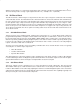
(b) TDM Mode
Internal
Processing
Nodes
(a) Discrete Mode − For I
2
S Format, Polarity
of LRCLK Opposite That Shown
Internal
Processing
Nodes
Internal
Processing
Nodes
Internal
Processing
Nodes
Internal
Processing
Nodes
Internal
Processing
Nodes
Internal
Processing
Nodes
Internal
Processing
Nodes
Figure 3−7. Serial Input Port to Processing Node Topology