
Datasheet


SN65LVDS387, SN75LVDS387, SN65LVDS389
SN75LVDS389, SN65LVDS391, SN75LVDS391
HIGH-SPEED DIFFERENTIAL LINE DRIVERS
SLLS362D – SEPTEMBER 1999 – REVISED MAY 2001
3
POST OFFICE BOX 655303 • DALLAS, TEXAS 75265
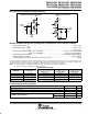
equivalent input and output schematic diagrams
7 V
300 kΩ
50 Ω
V
CC
A or EN
Input
V
CC
5 Ω
7 V
Y or Z
Output
EQUIVALENT OF EACH A OR EN INPUT TYPICAL OF ALL OUTPUTS
10 kΩ
absolute maximum ratings over operating free-air temperature (unless otherwise noted)
†
Supply voltage range, V
CC
–0.5 V to 4 V. . . . . . . . . . . . . . . . . . . . . . . . . . . . . . . . . . . . . . . . . . . . . . . . . . . . . . . . . .
Input voltage range: Inputs –0.5 V to 6 V. . . . . . . . . . . . . . . . . . . . . . . . . . . . . . . . . . . . . . . . . . . . . . . . . . . . . . . . .
Y or Z –0.5 V to 4 V. . . . . . . . . . . . . . . . . . . . . . . . . . . . . . . . . . . . . . . . . . . . . . . . . . . . . . . . .
Electrostatic discharge: SN65’ (Y, Z, and GND) Class 3, A:15 kV, B: 500 V. . . . . . . . . . . . . . . . . . . . . . . . . . . . .
SN75’ (Y, Z, and GND) Class 3, A:4 kV, B: 400 V. . . . . . . . . . . . . . . . . . . . . . . . . . . . . .
Continuous power dissipation (see Dissipation Rating Table). . . . . . . . . . . . . . . . . . . . . . . . . . . . . . . . . . . . . . . .
Storage temperature range –65°C to 150°C. . . . . . . . . . . . . . . . . . . . . . . . . . . . . . . . . . . . . . . . . . . . . . . . . . . . . . . .
Lead temperature 1,6 mm (1/16 in) from case for 10 seconds 260°C. . . . . . . . . . . . . . . . . . . . . . . . . . . . . . . . . .
†
Stresses beyond those listed under “absolute maximum ratings” may cause permanent damage to the device. These are stress ratings only, and
functional operation of the device at these or any other conditions beyond those indicated under “recommended operating conditions” is not
implied. Exposure to absolute-maximum-rated conditions for extended periods may affect device reliability.
NOTES: 1. All voltage values, except differential I/O bus voltages, are with respect to network ground terminal.
2. Tested in accordance with MIL-STD-883C Method 3015.7.
DISSIPATION RATING TABLE
PACKAGE
T
A
≤ 25°C
DERATING FACTOR
‡
ABOVE T
A
= 25°C
T
A
= 70°C
POWER RATING
T
A
= 85°C
POWER RATING
D 950 mW 7.6 mW/°C 608 mW 494 mW
DBT 1071 mW 8.5 mW/°C 688 mW 556 mW
DGG 2094 mW 16.7 mW/°C 1342 mW 1089 mW
PW 774 mW 6.2 mW/°C 496 mW 402 mW
‡
This is the inverse of the junction-to-ambient thermal resistance when board-mounted (low-k) and with no air flow.
recommended operating conditions
MIN NOM MAX UNIT
Supply voltage, V
CC
3 3.3 3.6 V
High-level input voltage, V
IH
2 V
Low-level input voltage, V
IL
0.8 V
O
p
erating free-air tem
p
erature T
A
SN75’ 0 70 °C
O erating
free
-
air
tem erature
,
T
A
SN65’ –40 85 °C