
Datasheet


www.ti.com
Data +
Data -
Clk +
Clk -
Video
Patterm
Generator
800 mVppor
1200 mVpp
Differential
Coax
Coax
Coax
Coax
Coax
Coax
Coax
Coax
SN 75 DP 129
SMA
SMA
SMA
SMA
Avcc
(4)
R
T
R
T
(5)
AVcc
R
T
R
T
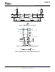
Jitter Test
Instrument
(2,3)
TTP 4
TTP 2TTP 1
FR 4 PCBtrace
(1)
&
ACcouplingCaps
FR 4 PCBtrace
RX
+EQ
OUT
RX
+EQ
OUT
SMA
SMA
SMA
SMA
TTP 3
Jitter Test
Instrument
(2,3)
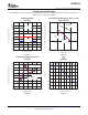
Driver
50 W
+
-
I
OS
50 W
0Vor3.6V
SN75DP129
SLAS583A – JANUARY 2008 – REVISED MARCH 2008
(1) The FR4 trance between TTP1 and TTP2 is designed to emulate 8 inches of FR4, a connector, and another 8 inches
if FR4.
(2) All jitter is measured at a BER of 10
– 12
(3) Residual jitter reflects the total jitter measured at TTP4 minus the jitter measured at TTP1.
(4) AVCC = 3.3 V
(5) R
T
= 50 Ω
Figure 16. TMDS Jitter Measurements
Figure 17. TMDS Main Link Short Circuit Output Circuit
14 Submit Documentation Feedback Copyright © 2008, Texas Instruments Incorporated
Product Folder Link(s): SN75DP129