
Datasheet


SN75976A, SN55976A
9-CHANNEL DIFFERENTIAL TRANSCEIVER
SLLS218B – MAY 1995 – REVISED MAY 1997
3
POST OFFICE BOX 655303 • DALLAS, TEXAS 75265
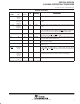
Terminal Functions
TERMINAL
Logic
I/O
Termination
DESCRIPTION
NAME NO.
g
Level
I/O
Termination
DESCRIPTION
1A to 9A 4,6,8,10,
19,21,23,
25,27
TTL I/O Pullup 1A to 9A carry data to and from the communication controller.
1B– to 9B– 29,31,33,
35,37,.46,
48,50,52
RS-485 I/O Pulldown 1B– to 9B– are the inverted data signals of the balanced pair to/from
the bus.
1B+ to 9B+ 30,32,34,
36,38,47,
49,51,53
RS-485 I/O Pullup 1B+ to 9B+ are the noninverted data signals of the balanced pair to/from
the bus.
BSR 2 TTL Input Pullup BSR is the bit significant response. BSR disables receivers 1 through 8 and
enables wired-OR drivers when BSR and DE/RE
and CDE1 or CDE2 are
high. Channel 9 is placed in a high-impedance state with BSR high.
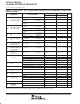
CDE0 54 TTL Input Pulldown CDE0 is the common driver enable 0. Its input signal enables all drivers
when CDE0 and 1DE/RE
– 9DE/RE are high.
CDE1 55 TTL Input Pulldown CDE1 is the common driver enable 1. Its input signal enables drivers
1 to 4 when CDE1 is high and BSR is low.
CDE2 56 TTL Input Pulldown CDE2 is the common driver enable 2. When CDE2 is high and BSR is low,
drivers 5 to 8 are enabled.
CRE 3 TTL Input Pullup CRE is the common receiver enable. When high, CRE disables receiver
channels 5 to 9.
1DE/RE to
9DE/RE
5,7,9,11,
20,22,24,
26,28
TTL Input Pullup 1DE/RE–9DE/RE are direction controls that transmit data to the bus when
it and CDE0 are high. Data is received from the bus when
1DE/RE
–9DE/RE and CRE and BSR are low and CDE1 and CDE2 are
low.
GND 1,13,14,
15,16,17,
40,41,42,
43,44
NA Power NA GND is the circuit ground. All GND terminals except terminal 1 are
physically tied to the die pad for improved thermal conductivity.
†
V
CC
12,18,39,
45
NA Power NA Supply voltage
†
Terminal 1 must be connected to signal ground for proper operation.