
Datasheet


SLLS025A − JULY 1986
3−9
POST OFFICE BOX 655303 • DALLAS, TEXAS 75265
POST OFFICE BOX 1443
• HOUSTON, TEXAS 77251−1443
APPLICATION INFORMATION
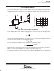
A faster, more efficient drive circuit uses an active pullup as well as an active pulldown output configuration,
referred to as a totem-pole output. The SN75372 driver provides the high speed, totem-pole drive desired in
an application of this type, see Figure 13(a). The resulting faster switching speeds are shown in Figure 13(b).
5 V
TLC555P
1/2 SN75372
M
t − Time − µs
(b)
(a)
IRF151
48 V
4
3
2
1
0
0 0.5 1 1.5 2 2.5 3
V0H − VOL − Gate Voltage − V
V
OH
V
OL
7
48
3
5
12
6
Figure 14. Power MOSFET Drive Using SN75372
Power MOSFET drivers must be capable of supplying high peak currents to achieve fast switching speeds as
shown by the equation
I
pk
+
VC
t
r
where C is the capacitive load, and t
r
is the desired drive time. V is the voltage that the capacitance is charged
to. In the circuit shown in Figure 13(a), V is found by the equation
V = V
OH
− V
OL
Peak current required to maintain a rise time of 100 ns in the circuit of Figure 13(a) is
I
PK
+
(3 * 0)4(10
*9
)
100(10
*9
)
+ 120 mA
Circuit capacitance can be ignored because it is very small compared to the input capacitance of the IRF151.
With a V
CC
of 5 V, and assuming worst-cast conditions, the gate drive voltage is 3 V.
For applications in which the full voltage of V
CC2
must be supplied to the MOSFET gate, the SN75374 quad
MOSFET driver should be used.