
Datasheet


SN55107A, SN75107A, SN75107B, SN75108A
DUAL LINE RECEIVERS
SLLS069D – JANUARY 1977 – REVISED APRIL 1998
11
POST OFFICE BOX 655303 • DALLAS, TEXAS 75265
APPLICATION INFORMATION
C
R
T
R
T
R
T
R
T
Drivers
SN55110A, SN75110A,
SN75112
Receiver 1 Receiver 2 Receiver 4
Driver 1 Driver 3 Driver 4
Location 1 Location 3 Location 4
Strobes
Receivers
‘107A, SN75107B,
SN75108A
Location 2
Data
Input
Inhibit
A
B
C
D
A
BB
A
C
DD
YY Y
Strobes Strobes
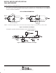
Figure 12. Typical Differential Party Line
unbalanced or single-line systems
These dual line circuits also can be used in unbalanced or single-line systems. Although these systems do not
offer the same performance as balanced systems for long lines, they are adequate for very short lines where
environmental noise is not severe.
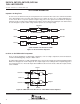
The receiver threshold level is established by applying a dc reference voltage to one receiver input terminal.
The signal from the transmission line is applied to the remaining input. The reference voltage should be
optimized so that signal swing is symmetrical about it for maximum noise margin. The reference voltage should
be in the range of –3 V to 3 V. It can be provided by a voltage supply or by a voltage divider from an available
supply voltage.
A single-ended output from a driver can be used in single-line systems. Coaxial or shielded line is preferred for
minimum noise and crosstalk problems. For large signal swings, the high output current (typically 27 mA) of the
SN75112 is recommended. Drivers can be paralleled for higher current. When using only one channel of the
line drivers, the other channel should be inhibited and/or have its outputs grounded.
Input
V
ref
Input
Inhibit
SN55110A, SN75110A, SN75112
A
B
C
D
Output
V
O
= –I
O
• R
R
‘107A, SN75107B, SN75108A
Strobes
Output
Figure 13. Single-Ended Operation