
Datasheet


SN54LVTH18504A, SN54LVTH182504A, SN74LVTH18504A, SN74LVTH182504A
3.3-V ABT SCAN TEST DEVICES
WITH 20-BIT UNIVERSAL BUS TRANSCEIVERS
SCBS667B – JULY 1996 – REVISED JUNE 1997
22
POST OFFICE BOX 655303 • DALLAS, TEXAS 75265
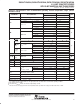
simultaneous PSA and binary count up (PSA/COUNT)
Data appearing at the selected device input-mode I/O pins is compressed into a 20-bit parallel signature in the
shift-register elements of the selected input-mode BSCs on each rising edge of TCK. At the same time, a 20-bit
binary count-up pattern is generated in the shift-register elements of the selected output-mode BSCs on each
rising edge of TCK, updated in the shadow latches, and applied to the associated device I/O pins on each falling
edge of TCK. Figures 11 and 12 show the 20-bit linear-feedback shift-register algorithms through which the
signature is generated. An initial seed value should be scanned into the BSR before performing this operation.
B8-I/O B7-I/O B6-I/O B5-I/O B4-I/O B3-I/O B2-I/O B1-I/OB10-I/O
A7-I/O A6-I/O A5-I/O A4-I/O A3-I/O A2-I/O A1-I/OA8-I/OA10-I/O
A17-I/O A16-I/O A15-I/O A14-I/O A13-I/O A12-I/O A11-I/OA18-I/OA20-I/O
B18-I/O B17-I/O B16-I/O B15-I/O B14-I/O B13-I/O B12-I/O B11-I/OB20-I/O
B9-I/O
A9-I/O
A19-I/O
B19-I/O
=
=
MSB
LSB
Figure 11. 20-Bit PSA/COUNT Configuration (OEAB = 0, OEBA = 1)