
Datasheet


www.ti.com
DESCRIPTION/ORDERING INFORMATION (CONTINUED)
GQL OR ZQL PACKAGE
(TOP VIEW)
J
H
G
F
E
D
C
B
A
21 3 4 65
K
GRD OR ZRD PACKAGE
(TOP VIEW)
J
H
G
F
E
D
C
B
A
21 3 4 65
SN74LVCH16373A
16-BIT TRANSPARENT D-TYPE LATCH
WITH 3-STATE OUTPUTS
SCAS568M – MARCH 1996 – REVISED FEBRUARY 2006
The SN74LVCH16373A is particularly suitable for implementing buffer registers, I/O ports, bidirectional bus
drivers, and working registers. It can be used as two 8-bit latches or one 16-bit latch. When the latch-enable (LE)
input is high, the Q outputs follow the data (D) inputs. When LE is taken low, the Q outputs are latched at the
levels set up at the D inputs.
A buffered output-enable ( OE) input can be used to place the eight outputs in either a normal logic state (high or
low logic levels) or the high-impedance state. In the high-impedance state, the outputs neither load nor drive the
bus lines significantly. The high-impedance state and increased drive provide the capability to drive bus lines
without interface or pullup components.
OE does not affect internal operations of the latch. Old data can be retained or new data can be entered while
the outputs are in the high-impedance state.
Inputs can be driven from either 3.3-V or 5-V devices. This feature allows the use of this device as a translator in
a mixed 3.3-V/5-V system environment.
To ensure the high-impedance state during power up or power down, OE should be tied to V
CC
through a pullup
resistor; the minimum value of the resistor is determined by the current-sinking capability of the driver.
This device is fully specified for partial-power-down applications using I
off
. The I
off
circuitry disables the outputs,
preventing damaging current backflow through the device when it is powered down.
Active bus-hold circuitry holds unused or undriven inputs at a valid logic state. Use of pullup or pulldown resistors
with the bus-hold circuitry is not recommended.
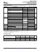
TERMINAL ASSIGNMENTS
(1)
(56-Ball GQL/ZQL Package)
1 2 3 4 5 6
A 1 OE NC NC NC NC 1LE
B 1Q2 1Q1 GND GND 1D1 1D2
C 1Q4 1Q3 V
CC
V
CC
1D3 1D4
D 1Q6 1Q5 GND GND 1D5 1D6
E 1Q8 1Q7 1D7 1D8
F 2Q1 2Q2 2D2 2D1
G 2Q3 2Q4 GND GND 2D4 2D3
H 2Q5 2Q6 V
CC
V
CC
2F6 2D5
J 2Q7 2Q8 GND GND 2D8 2D7
K 2 OE NC NC NC NC 2LE
XXXXXXX
(1) NC – No internal connection
TERMINAL ASSIGNMENTS
(1)
(54-Ball GRD/ZRD Package)
1 2 3 4 5 6
A 1Q1 NC 1 OE 1LE NC 1D1
B 1Q3 1Q2 NC NC 1D2 1D3
C 1Q5 1Q4 V
CC
V
CC
1D4 1D5
D 1Q7 1Q6 GND GND 1D6 1D7
E 2Q1 1Q8 GND GND 1D8 2D1
F 2Q3 2Q2 GND GND 2D2 2D3
G 2Q5 2Q4 V
CC
V
CC
2D4 2D5
H 2Q7 2Q6 NC NC 2D6 2D7
J 2Q8 NC 2 OE 2LE NC 2D8
(1) NC – No internal connection
2
Submit Documentation Feedback