
Datasheet


www.ti.com
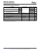
RECEIVER ELECTRICAL CHARACTERISTICS
SN65MLVD201 , SN65MLVD203
SN65MLVD206 , SN65MLVD207
SLLS558C – DECEMBER 2002 – REVISED JANUARY 2007
over recommended operating conditions unless otherwise noted
(1)
PARAMETER TEST CONDITIONS MIN TYP
(1)
MAX UNIT
Type 1 50
V
IT+
Positive-going differential input voltage threshold mV
Type 2 150
Type 1 – 50
See Figure 9 and Table 1 and
V
IT-
Negative-going differential input voltage threshold mV
Table 2
Type 2 50
Type 1 25
V
HYS
Differential input voltage hysteresis, (V
IT+
– V
IT
) mV
Type 2 0
V
OH
High-level output voltage I
OH
= – 8 mA 2.4 V
V
OL
Low-level output voltage I
OL
= 8 mA 0.4 V
I
IH
High-level input current ( RE) V
IH
= 2 V – 10 0 µ A
I
IL
Low-level input current ( RE) V
IL
= 0.8 V – 10 0 µ A
I
OZ
High-impedance output current V
O
= 0 V or 3.6 V – 10 15 µ A
V
I
= 0.4 sin(30E6 π t) + 0.5 V,
(2)
C
A
or C
B
Input capacitance 3 pF
Other input at 1.2 V
C
AB
Differential input capacitance V
AB
= 0.4 sin(30E6 π t) V
(2)
2.5 pF
C
A/B
Input capacitance balance, (C
A/
C
B
) 0.99 1.01
(1) All typical values are at 25 ° C and with a 3.3-V supply voltage.
(2) HP4194A impedance analyzer (or equivalent)
4 Submit Documentation Feedback Copyright © 2002 – 2007, Texas Instruments Incorporated
Product Folder Link(s): SN65MLVD201 SN65MLVD203 SN65MLVD206 SN65MLVD207