
Datasheet


SN65LVDS315
www.ti.com
SLLS881F –DECEMBER 2007–REVISED SEPTEMBER 2012
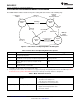
DEVICE ELECTRICAL CHARACTERISTICS
over operating free-air temperature range (unless otherwise noted)
PARAMETER TEST CONDITIONS MIN TYP
(1)
MAX UNIT
V
DDIO
= V
DDD
= V
DDA
, R
L(CLK)
= R
L(D0)
= 100 Ω, V
IH
=V
DDIO
, FSEL = V
IL
, f
DCLK
= 3.5 MHz 4.8
V
IL
=0V, TXEN and MODE at V
DDD
, typical blanking power
FSEL = V
IL
, f
DCLK
= 11 MHz 7.6
test pattern. See Table 6
FSEL = V
IH
, f
DCLK
= 11 MHz 5.9
FSEL = V
IH
, f
DCLK
= 26 MHz 9.6
mA
V
DDIO
= V
DDD
= V
DDA
, R
L(CLK)
= R
L(D0)
= 100 Ω, V
IH
=V
DDIO
, FSEL = V
IL
, f
DCLK
= 3.5 MHz 5.7 8.1
V
IL
=0V, TXEN and MODE at V
DDD
, Alternating (worst-case)
FSEL = V
IL
, f
DCLK
= 11 MHz 8.9 11.2
1010 serial bit pattern. See Table 7
FSEL = V
IH
, f
DCLK
= 11 MHz 7.2 9.5
Supply
FSEL = V
IH
, f
DCLK
= 26 MHz 11.3 13.3
I
DD
current
Standby mode (TXEN at V
DD
) V
DDIO
= V
DDD
= V
DDA
, 0.2 10
R
L(CLK)
= R
L(D0)
= 100 Ω, V
IH
=V
DDIO
, V
IL
=0
Shutdown mode (TXEN at GND) 0.2 10
V, TXEN and MODE at V
DDD
, All inputs
held static high (V
IH
) or static low (V
IL
)
μA
Standby mode (TXEN at V
DD
) V
DDIO
= V
DDD
= V
DDA
, 0.02 10
R
L(CLK)
= R
L(D0)
= 100 Ω, V
IH
=V
DDIO
, V
IL
=0
Shutdown mode (TXEN at GND) 0.03 5
V, TXEN and Mode = V
IL
; D[7:0] VS, HS,
and DCLK left open
(1) All typical values are at 25°C and with 1.8 V supply unless otherwise noted.
OUTPUT ELECTRICAL CHARACTERISTICS
over recommended operating conditions (unless otherwise noted)
PARAMETER TEST CONDITIONS MIN TYP
(1)
MAX UNIT
subLVDS OUTPUTS (DOUT+, DOUT–, CLK+, and CLK–)
V
OCM
(SS) Steady-state common-mode output voltage 0.8 0.925 1.0 V
|V
OD
| Differential output voltage magnitude 100 170 250 mV
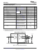
See Figure 9, Output load see
Figure 13
|V
DOUT+
– V
DOUT–
|, |V
CLK+
– V
CLK–
|
Δ|V
OD
| Change in differential output voltage between logic states –10 10 mV
ZOD Differential small-signal output impedance TXEN at VDD 5 kΩ
I
OSD
Differential short-circuit output current V
OD
= 0 V; f
DCLK
= 26 MHz 1 10 mA
I
OZ
High-impedance state output current V
O
= 0 V or V
DD
(max), TXEN at GND –3 3 μA
(1) All typical values are at 25°C and with 1.8V supply unless otherwise noted.
INPUT ELECTRICAL CHARACTERISTICS
over recommended operating conditions (unless otherwise noted)
PARAMETER TEST CONDITIONS MIN TYP
(1)
MAX UNIT
Dx, VS, HS, DCLK
I
IL(hold)
Bus hold input current
(2)
V
DDIO
= 1.65 V and V
DDIO
= 3.6 V 15 100 μA
I
IH(hold)
Bus hold input current
(3)
V
DDIO
= 1.65 V and V
DDIO
= 3.6 V –15 –100 μA
C
IN
Input capacitance 1.5 pF
MODE, TXEN, FSEL
I
IL
High-level input current V
IH
= 0.7 V
DDD
, See Figure 9 –200 –0.7 200 nA
I
IH
Low-level input current V
IL
= 0.3 V
DDD
, See Figure 9 –200 0.5 200 nA
C
IN
Input capacitance V
I
= TBD 1.5 pF
(1) All typical values are at 25°C and with 1.8 V supply unless otherwise noted.
(2) I
IL(hold)
is the input current the bus-hold input stage is able to source to maintain a low logic level; The bus-hold current becomes minimal
as the input approaches GND. I
IL(hold)
is the least amount of current a camera output must source to overcome the bus hold and force a
high signal.
(3) I
IH(hold)
is the input current the bus-hold input stage is able to source to maintain a high logic level. The bus-hold current becomes
minimal as the input approaches V
DDIO
. I
IL(hold)
is the least amount of current a camera output must be able source to overcome the bus
hold and switch to a low signal.
Copyright © 2007–2012, Texas Instruments Incorporated Submit Documentation Feedback 15
Product Folder Links :SN65LVDS315