
Datasheet


www.ti.com
FUNCTION TABLES
SN65LVDM176
SLLS320D – DECEMBER 1998 – REVISED JULY 2000
These devices have limited built-in ESD protection. The leads should be shorted together or the device placed in conductive foam
during storage or handling to prevent electrostatic damage to the MOS gates.
AVAILABLE OPTIONS
PACKAGE
T
A
SMALL OUTLINE MSOP
(D)
(1)
(DGK)
(1)
–40°C to 85°C SN65LVDM176D SN65LVDM176DGK
(1) The D package is available taped and reeled. Add the suffix R to the device type(e.g.,
SN65LVDM176DR).
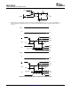
DRIVER
(1)
OUTPUTS
INPUT ENABLE
D DE
A B
L H L H
H H H L
Open H L H
X L Z Z
(1) H = high level, L = low level, X = irrelevant, Z = high impedance
RECEIVER
(1)
DIFFERENTIAL INPUTS ENABLE OUTPUT
V
ID
= V
A
- V
B
RE R
V
ID
≥ 50 mV L H
50 mV < V
ID
< 50 mV L ?
V
ID
≤ -50 mV L L
Open L H
X H Z
(1) H = high level, L = low level, X = irrelevant, Z = high impedance
2
Submit Documentation Feedback