
Datasheet


SN65HVD3080E
SN65HVD3083E
SN65HVD3086E
SLLS771E –NOVEMBER 2006–REVISED NOVEMBER 2012
www.ti.com
This integrated circuit can be damaged by ESD. Texas Instruments recommends that all integrated circuits be handled with
appropriate precautions. Failure to observe proper handling and installation procedures can cause damage.
ESD damage can range from subtle performance degradation to complete device failure. Precision integrated circuits may be more
susceptible to damage because very small parametric changes could cause the device not to meet its published specifications.
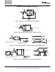
ORDERING INFORMATION
PART NUMBER SIGNALING RATE PACKAGE
(1)
MARKED AS
SN65HVD3080E 200 kbps BTT
SN65HVD3083E 1 Mbps DGS, DGSR 10-pin MSOP
(2)
BTU
BTF
SN65HVD3086E 20 Mbps
D 14-pin SOIC HVD3086
(1) For the most current package and ordering information, see the Package Option Addendum at the end of this document, or see the TI
website at www.ti.com.
(2) The R suffix indicated tape and reel.
ABSOLUTE MAXIMUM RATINGS
over operating free-air temperature range unless otherwise noted
(1)
UNIT
V
CC
Supply voltage range
(2)
–0.3 V to 7 V
V
(A)
, V
(B)
, V
(Y)
, V
(Z)
Voltage range at any bus terminal (A, B, Y, Z) –9 V to 14 V
Voltage input, transient pulse through 100 Ω.
V
(TRANS)
–50 to 50 V
See Figure 10 (A, B, Y, Z)
V
I
Input voltage range (D, DE, RE) -0.3 V to V
CC
+0.3 V
P
D
Continuous total power dissipation See the dissipation rating table
T
J
Junction temperature 170°C
(1) Stresses beyond those listed under absolute maximum ratings may cause permanent damage to the device. These are stress ratings
only, and functional operation of the device at these or any other conditions beyond those indicated under recommended operating
conditions is not implied. Exposure to absolute-maximum-rated conditions for extended periods may affect device reliability.
(2) All voltage values, except differential I/O bus voltages, are with respect to network ground terminal.
POWER DISSIPATION RATINGS
DERATING FACTOR
(1)
PACKAGE T
A
< 25°C T
A
= 85°C
ABOVE T
A
< 25°C
10-pin MSOP (DGS) 463 mW 3.71 mW/°C 241 mW
14-pin SOIC (D) 765 mW 6.1 mW/°C 400 mW
(1) This is the inverse of the junction-to-ambient thermal resistance when board-mounted and with no air flow.
ELECTROSTATIC DISCHARGE PROTECTION
PARAMETER TEST CONDITIONS MIN TYP MAX UNIT
Human Body Model
(1)
A,B,Y,Z, and GND 16 kV
All pins 6 kV
Charged Device Mode
(2)
All pins 1.5 kV
Machine Model
(3)
All pins 400 V
(1) Tested in accordance JEDEC Standard 22, Test Method A114-A. Bus pin stressed with respect to a common connection of GND and
V
CC
.
(2) Tested in accordance JEDEC Standard 22, Test Method C101.
(3) Tested in accordance JEDEC Standard 22, Test Method A115.
2 Submit Documentation Feedback Copyright © 2006–2012, Texas Instruments Incorporated
Product Folder Links: SN65HVD3080E SN65HVD3083E SN65HVD3086E