
Datasheet


V
OD
RL =54
1%
W
±
50 W
t
PLH
t
PHL
50% 50%
3V
» 2V
» –2V
90%
10%
0V
V
I
V
OD
t
r
t
f
C =50pF 20%
L
±
C IncludesFixture
L
andInstrumentation
Capacitance
D
A
B
DE
V
CC
V
I
Input
Generator
90%
0V
10%
S0303-01
0.5V
3V
0V
V
OH
» 0V
t
PHZ
t
PZH
50% 50%
V
I
V
O
50%
90%
R =110
L
W
± 1%
Input
Generator
50 W
3V
S1
C =50pF
L
±20%
C IncludesFixture
L
andInstrumentation
Capacitance
D
A
B
DE
V
O
V
I
S0304-01
Input
Generator
50 W
3V
V
O
S1
3V
50%
50%
50%
t
PZL
t
PLZ
10%
» 3V
0V
V
OL
V
I
V
O
R =110
L
W
±1%
CL =50pF ±20%
C IncludesFixture
L
andInstrumentation
Capacitance
D
A
B
DE
V
I
» 3V
S0305-01
SN65HVD1785, SN65HVD1786
SN65HVD1787, SN65HVD1791
SN65HVD1792, SN65HVD1793
www.ti.com
SLLS872H –JANUARY 2008–REVISED FEBRUARY 2010
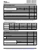
PARAMETER MEASUREMENT INFORMATION (continued)
Figure 3. Measurement of Driver Differential Output Rise and Fall Times and Propagation Delays
NOTE: D at 3 V to test non-inverting output, D at 0 V to test inverting output.
Figure 4. Measurement of Driver Enable and Disable Times With Active High Output and Pulldown Load
NOTE: D at 0 V to test non-inverting output, D at 3 V to test inverting output.
Figure 5. Measurement of Driver Enable and Disable Times With Active-Low Output and Pullup Load
Copyright © 2008–2010, Texas Instruments Incorporated Submit Documentation Feedback 7
Product Folder Link(s): SN65HVD1785, SN65HVD1786 SN65HVD1787, SN65HVD1791 SN65HVD1792, SN65HVD1793