
Datasheet


V
O1
R
1
R
5
R
6
V
O
V
IN
V
O2
R
4
A
1
-
+
V
LP
V
BP
V
HP
V
IN
R
4
R
1
+
-
R
2
C
2
A
2
+
-
R
3
C
3
A
3
+
-
A
1
R
6
R
5
dB
0
f
1
-20dB/dec
f (Hz)
|H
|
|H
O
|
f
2
20dB/dec
SM73308
www.ti.com
SNOSB90B –JUNE 2011–REVISED APRIL 2013
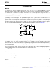
Figure 49. Bandpass filter Transfer Function
STATE VARIABLE ACTIVE FILTER
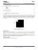
State variable active filters are circuits that can simultaneously represent high pass, band pass, and low pass
filters. The state variable active filter uses three separate amplifiers to achieve this task. A typical state variable
active filter is shown in Figure 50. The first amplifier in the circuit is connected as a gain stage. The second and
third amplifiers are connected as integrators, which means they behave as low pass filters. The feedback path
from the output of the third amplifier to the first amplifier enables this low frequency signal to be fed back with a
finite and fairly low closed loop gain. This is while the high frequency signal on the input is still gained up by the
open loop gain of the 1st amplifier. This makes the first amplifier a high pass filter. The high pass signal is then
fed into a low pass filter. The outcome is a band pass signal, meaning the second amplifier is a band pass filter.
This signal is then fed into the third amplifiers input and so, the third amplifier behaves as a simple low pass
filter.
Figure 50. State Variable Active Filter
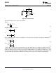
The transfer function of each filter needs to be calculated. The derivations will be more trivial if each stage of the
filter is shown on its own.
The three components are:
Copyright © 2011–2013, Texas Instruments Incorporated Submit Documentation Feedback 17
Product Folder Links: SM73308