
Datasheet


f
1
=
1
2SR
1
C
1
f
2
=
1
2SR
2
C
2
H
O
=
-R
2
R
1
j (f/f
1
)
[1 + j (f/f
1
)]
H = H
O
[1 + j (f/f
2
)]
V
i
R
1
R
2
+
-
V
OUT
C
2
C
1
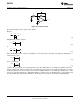
dB
0
f = f
o
-20dB/dec
f (Hz)
|H|
|H
O
|
SM73308
SNOSB90B –JUNE 2011–REVISED APRIL 2013
www.ti.com
Figure 47. Highpass Filter Transfer Function
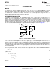
BAND PASS FILTER
Figure 48. Bandpass Filter
Combining a low pass filter and a high pass filter will generate a band pass filter. In this network the input
impedance forms the high pass filter while the feedback impedance forms the low pass filter. Choosing the
corner frequencies so that f
1
< f
2
, then all the frequencies in between, f
1
≤ f ≤ f
2
, will pass through the filter while
frequencies below f
1
and above f
2
will be cut off.
The transfer function can be easily calculated using the same methodology as before.
where
• (18)
The transfer function is presented in the following figure.
16 Submit Documentation Feedback Copyright © 2011–2013, Texas Instruments Incorporated
Product Folder Links: SM73308