
Datasheet


SLVS077D – APRIL 1977 – REVISED FEBRUARY 2003
4
POST OFFICE BOX 655303 • DALLAS, TEXAS 75265
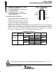
error amplifier section
PARAMETER
TEST
SG2524 SG3524
UNIT
PARAMETER
TEST
CONDITIONS
†
MIN TYP
‡
MAX MIN TYP
‡
MAX
UNIT
V
IO
Input offset voltage V
IC
= 2.5 V 0.5 5 2 10 mV
I
IB
Input bias current V
IC
= 2.5 V 2 10 2 10 µA
Open-loop voltage amplification 72 80 60 80 dB
V
ICR
Common-mode input voltage range T
A
= 25°C
1.8 to
3.4
1.8 to
3.4
V
CMMR Common-mode rejection ratio 70 70 dB
B
1
Unity-gain bandwidth 3 3 MHz
Output swing T
A
= 25°C 0.5 3.8 0.5 3.8 V
†
For conditions shown as MIN or MAX, use the appropriate value specified under recommended operating conditions.
‡
All typical values, except for temperature coefficients, are at T
A
= 25°C
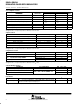
output section
PARAMETER
TEST CONDITIONS
†
MIN TYP
‡
MAX
UNIT
V
(BR)CE
Collector-emitter breakdown voltage 40 V
Collector off-state current V
CE
= 40 V 0.01 50 µA
V
sat
Collector-emitter saturation voltage I
C
= 50 mA 1 2 V
V
O
Emitter output voltage V
C
= 20 V, I
E
= –250 µA 17 18 V
t
r
Turn-off voltage rise time R
C
= 2 kΩ 0.2 µs
t
f
Turn-on voltage fall time R
C
= 2 kΩ 0.1 µs
†
For conditions shown as MIN or MAX, use the appropriate value specified under recommended operating conditions.
‡
All typical values, except for temperature coefficients, are at T
A
= 25°C.
comparator section
PARAMETER
TEST CONDITIONS
†
MIN TYP
‡
MAX
UNIT
Maximum duty cycle, each output 45%
V
Inp t threshold oltage at COMP
Zero duty cycle 1
V
V
IT
Input threshold voltage at COMP
Maximum duty cycle
3.5
V
I
IB
Input bias current –1 µA
†
For conditions shown as MIN or MAX, use the appropriate value specified under recommended operating conditions.
‡
All typical values, except for temperature coefficients, are at T
A
= 25°C.
current limiting section
PARAMETER
TEST CONDITIONS
†
MIN TYP
‡
MAX
UNIT
V
I
Input voltage range (either input) –1 to1 V
V
(SENSE)
Sense voltage at T
A
= 25°C
V
(IN )
V
(IN )
≥ 50 mV V
(COMP)
2V
175 200 225 mV
Temperature coefficient of sense voltage
V
(IN+)
– V
(IN–)
≥ 50 mV, V
(COMP)
= 2 V
0.2 mV/°C
‡
All typical values, except for temperature coefficients, are at T
A
= 25°C.
total device
PARAMETER
TEST CONDITIONS MIN TYP
‡
MAX UNIT
I
st
Standby current
V
CC
= 40 V, IN–, CURR LIM+, C
T
, GND, COMP, EMIT 1, EMIT 2 grounded,
IN+ at 2 V, All other inputs and outputs open
8 10 mA
‡
All typical values, except for temperature coefficients, are at T
A
= 25°C.