
Datasheet


SCANSTA111
SNLS060K –AUGUST 2001–REVISED APRIL 2013
www.ti.com
LEVEL 1 PROTOCOL (ADDRESSING MODES)
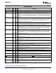
Table 3. SCANSTA111 Address Modes
Address Type Hex Address Binary Address TDO
B
State
Direct Address 00 to 39, 00000000 to 00111010 Normal IEEE Std. 1149.1
40 to 7F. 01000000 to 01111111
(80 to FF
(1)
) (10000000 to 11111111
(1)
)
Interrogation Address 3A 00111010 Force strong 0' or weak 1' as ones-complement
address is shifted out.
Broadcast Address 3B 00111011 Always TRI-STATED
Multi-Cast Group 0 3C 00111100 Always TRI-STATED
Multi-Cast Group 1 3D 00111101 Always TRI-STATED
Multi-Cast Group 2 3E 00111110 Always TRI-STATED
Multi-Cast Group 3 3F 00111111 Always TRI-STATED
(1) Hex addresses 80' to FF' are only available when using the eighth address bit in the HDL version of the SCANSTA111. The Silicon part
has seven address lines and will treat the most-significant address bit as a don't care.
The SCANSTA111 supports single and multiple modes of addressing a 'STA111. The single mode selects one
'STA111 and is called Direct Addressing. More than one 'STA111 device can be selected via the Broadcast and
Multi-Cast Addressing modes.
DIRECT ADDRESSING: The 'STA111 enters the Wait-For-Address state when:
1. its TAP Controller enters the Test-Logic-Reset state, or
2. its instruction register is updated with the GOTOWAIT instruction (while either selected or unselected).
Each 'STA111 within a scan network must be statically configured with a unique address via its S
(0-6)
inputs.
While the 'STA111 controller is in the Wait-For-Address state, data shifted into bits 6 through 0 of the instruction
register is compared with the address present on the S
(0-6)
inputs in the Update-IR state. If the seven (7) LSBs of
the instruction register match the address on the S
(0-6)
inputs, (see Figure 6) the 'STA111 becomes selected, and
is ready to receive Level 2 Protocol (i.e., further instructions). When the 'STA111 is selected, its device
identification register is inserted into the active scan chain.
All 'STA111s whose S
(0-6)
address does not match the instruction register address become unselected. An
unselected 'STA111 will remain unselected until either its TAP Controller enters the Test-Logic-Reset state, or its
instruction register is updated with the GOTOWAIT instruction.
BROADCAST ADDRESSING:
The Broadcast Address allows a tester to simultaneously select all 'STA111s in a test network. This mode is
useful in testing systems which contain multiple identical boards. To avoid bus contention between scan-path
output drivers on different boards, each 'STA111's TDO
B
buffer is always TRI-STATEd while in Broadcast mode.
In this configuration, the on-chip Linear Feedback Shift Register (LFSR) can be used to accumulate a test result
signature for each board that can be read back later by direct-addressing each board's 'STA111.
MULTICAST ADDRESSING:
As a way to make the broadcast mechanism more selective, the 'STA111 provides a Multi-cast addressing mode.
A 'STA111's multi-cast group register (MCGR) can be programmed to assign that 'STA111 to one of four (4)
Multi-Cast groups. When 'STA111s in the Wait-For-Address state are updated with a Multi-Cast address, all
'STA111s whose MCGR matches the Multi-Cast group will become selected. As in Broadcast mode, TDO
B
is
always TRI-STATEd while in Multi-cast mode.
10 Submit Documentation Feedback Copyright © 2001–2013, Texas Instruments Incorporated
Product Folder Links: SCANSTA111