
Datasheet


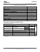


Table Of Contents
- FEATURES
- APPLICATIONS
- DESCRIPTION
- DATASHEET TABLE OF CONTENTS
- ENVIRONMENTAL AND ABSOLUTE MAXIMUM RATINGS
- ELECTRICAL CHARACTERISTICS
- TYPICAL CHARACTERISTICSThe electrical characteristic data has been developed from actual products tested at 25C. This data is considered typical for the converter. Applies to , , and .The temperature derating curves represent the conditions at which internal components are at or below the manufacturer's maximum operating temperatures. Derating limits apply to modules soldered directly to a 100 mm 100 mm double-sided PCB with 2 oz. copper. Applies to and .
- APPLICATION INFORMATION
- Tape & Reel and Tray Drawings

PTH05T210W
www.ti.com
...................................................................................................................................................... SLTS263I – AUGUST 2007 – REVISED MARCH 2009
ELECTRICAL CHARACTERISTICS (continued)
T
A
=25 ° C, V
I
= 5 V, V
O
= 3.3 V, C
I
= 1000 µ F, C
O
= 470 µ F OS-CON, and I
O
= I
O
max (unless otherwise stated)
PARAMETER TEST CONDITIONS MIN TYP MAX UNIT
12,000
Nonceramic 470
(5)
Capacitance
(6)
µ F
Value
w/out TurboTrans
Ceramic 5000
External output Equivalent series resistance (nonceramic) 3
(7)
m Ω
C
O
capacitance
See TT 12,000
Capacitance Value µ F
chart
(8) (9)
w/ TurboTrans
10,000
Capacitance × ESR product (C
O
× ESR) µ F × m Ω
(10)
MTBF Reliability Per Bellcore TR-332, 50% stress, T
A
= 40 ° C, ground benign 3.6
10
6
Hr
(5) A minimum value of external output capacitor is required for proper operation. Adding additional capacitance at the load further improves
transient response. See the Capacitor Application Information section for more guidance.
(6) This is the calculated maximum. This value includes both ceramic and non-ceramic capacitors. The minimum ESR requirement often
results in a lower value. See the related Application Information for more guidance.
(7) This is the minimum ESR for all the electrolytic (nonceramic) capacitance. Use 5 m Ω as the minimum when using manufacturer ' s
max-ESR values to calculate.
(8) Minimum capacitance is determined by the transient deviation requirement. A corresponding resistor, R
TT
is required for proper
operation. See the TurboTrans Selection section for guidance in selecting the capacitance and R
TT
value.
(9) This is the calculated maximum. This value includes both ceramic and non-ceramic capacitors.
(10) When calculating the Capacitance × ESR product use the capacitance and ESR values of a single capacitor. For an output capacitor
bank of several capacitor types and values, calculate the C × ESR product using the values of the capacitor that makes up the majority
of the capacitance.
Copyright © 2007 – 2009, Texas Instruments Incorporated Submit Documentation Feedback 5
Product Folder Link(s): PTH05T210W