
Datasheet


Table Of Contents
- FEATURES
- APPLICATIONS
- DESCRIPTION
- DATASHEET TABLE OF CONTENTS
- ENVIRONMENTAL AND ABSOLUTE MAXIMUM RATINGS
- ELECTRICAL CHARACTERISTICS
- TYPICAL CHARACTERISTICSThe electrical characteristic data has been developed from actual products tested at 25C. This data is considered typical for the converter. Applies to , , and .The temperature derating curves represent the conditions at which internal components are at or below the manufacturer's maximum operating temperatures. Derating limits apply to modules soldered directly to a 100 mm 100 mm double-sided PCB with 2 oz. copper. Applies to and .
- APPLICATION INFORMATION
- Tape & Reel and Tray Drawings
Notes on Use of Auto-Track™
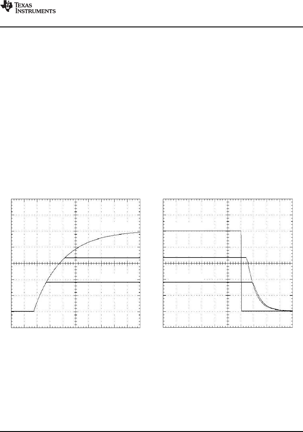
t − Time − 20 ms/div
V
O1
(1 V/div)
V
TRK
(1 V/div)
V
O2
(1 V/div)
t − Time − 200 µs/div
V
O1
(1 V/div)
V
TRK
(1 V/div)
V
O2
(1 V/div)
PTH05T210W
www.ti.com
...................................................................................................................................................... SLTS263I – AUGUST 2007 – REVISED MARCH 2009
Figure 16 shows the output voltage waveforms after input voltage is applied to the circuit. The waveforms, V
O
1
and V
O
2, represent the output voltages from the two power modules, U1 (3.3 V) and U2 (1.8 V), respectively.
V
TRK
, V
O
1, and V
O
2 are shown rising together to produce the desired simultaneous power-up characteristic.
The same circuit also provides a power-down sequence. When the input voltage falls below U3's voltage
threshold, the ground signal is re-applied to the common track control. This pulls the track inputs to zero volts,
forcing the output of each module to follow, as shown in Figure 17 . Power down is normally complete before the
input voltage has fallen below the modules' undervoltage lockout. This is an important constraint. Once the
modules recognize that an input voltage is no longer present, their outputs can no longer follow the voltage
applied at their track input. During a power-down sequence, the fall in the output voltage from the modules is
limited by the Auto-Track slew rate capability.
1. The Track pin voltage must be allowed to rise above the module set-point voltage before the module
regulates at its adjusted set-point voltage.
2. The Auto-Track function tracks almost any voltage ramp during power up, and is compatible with ramp
speeds of up to 1 V/ms.
3. The absolute maximum voltage that may be applied to the Track pin is the input voltage V
I
.
4. The module cannot follow a voltage at its track control input until it has completed its soft-start initialization.
This takes about 20 ms from the time that a valid voltage has been applied to its input. During this period, it
is recommended that the Track pin be held at ground potential.
5. The Auto-Track function is disabled by connecting the Track pin to the input voltage (V
I
). When Auto-Track is
disabled, the output voltage rises at a quicker and more linear rate after input power has been applied.
Figure 16. Simultaneous Power Up Figure 17. Simultaneous Power Down
With Auto-Track Control With Auto-Track Control
Copyright © 2007 – 2009, Texas Instruments Incorporated Submit Documentation Feedback 23
Product Folder Link(s): PTH05T210W