
Datasheet


R
UVLO
1%
0.05 W
(Optional)
PTH04T230W
2
4
8
7
Track
VoAdj
Vo
TT
3
GND
GND
+Sense
5
L
O
A
D
−Sense
GND
+
10
Inhibit
INH/UVLO
Track
9
6
−Sense
+Sense
Vo
SYNC
1
SmartSync
C
O1
100 µF
Ceramic
(Required)
C
O2
150 µF
Non−Ceramic
(Required)
V
I
V
I
C
I
330 µF
(Required)
(Note B)
R
TT
1%
0.05 W
(Optional)
R
SET
1%
0.05 W
(Required)
(Note A)
TurboTransE
UDG−06046
+
R
UVLO
1%
0.05 W
(Optional)
PTH04T231W
2
4
8
7
Track
VoAdj
Vo
TT
3
GND
GND
+Sense
5
L
O
A
D
−Sense
GND
10
Inhibit
INH/UVLO
Track
9
6
−Sense
+Sense
Vo
SYNC
1
SmartSync
C
O
300 µF
Ceramic
(Required)
V
I
V
I
C
I
300 µF
(Required)
R
TT
1%
0.05 W
(Optional)
R
SET
1%
0.05 W
(Required)
(Note A)
TurboTransE
PTH04T230W , PTH04T231W
SLTS271C – SEPTEMBER 2006 – REVISED MARCH 2009 .............................................................................................................................................
www.ti.com
These devices have limited built-in ESD protection. The leads should be shorted together or the device placed in conductive foam
during storage or handling to prevent electrostatic damage to the MOS gates.
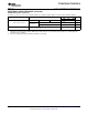
PTH04T230W
A. R
SET
required to set the output voltage to a value higher than 0.69 V. See the Electrical Characteristics table.
B. An additional 22- µ F ceramic input capacitor is recommended to reduce RMS ripple current.
PTH04T231W - Ceramic Capacitor Version
2 Submit Documentation Feedback Copyright © 2006 – 2009, Texas Instruments Incorporated
Product Folder Link(s): PTH04T230W PTH04T231W