
Datasheet


Designing for Fast Load Transients
PTH04T230W , PTH04T231W
www.ti.com
............................................................................................................................................. SLTS271C – SEPTEMBER 2006 – REVISED MARCH 2009
The transient response of the dc/dc converter has been characterized using a load transient with a di/dt of
2.5A/ µ s. The typical voltage deviation for this load transient is given in the Electrical Characteristics table using
the minimum required value of output capacitance. As the di/dt of a transient is increased, the response of a
converter ’ s regulation circuit ultimately depends on its output capacitor decoupling network. This is an inherent
limitation with any dc/dc converter once the speed of the transient exceeds its bandwidth capability.
If the target application specifies a higher di/dt or lower voltage deviation, the requirement can only be met with
additional low ESR ceramic capacitor decoupling. Generally, with load steps greater than 100A/ µ s, adding
multiple 10- µ F ceramic capacitors plus 10 × 1 µ F, and numerous high frequency ceramics ( ≤ 0.1 µ F) is all that is
required to soften the transient higher frequency edges. The PCB location of these capacitors in relation to the
load is critical. DSP, FPGA and ASIC vendors identify types, location and amount of capacitance required for
optimum performance. Low impedance buses, unbroken PCB copper planes, and components located as close
as possible to the high frequency devices are essential for optimizing transient performance.
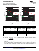
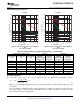
Table 3. Input/Output Capacitors
(1)
Capacitor Characteristics Quantity
Max Output Bus
(2)
Max
Ripple
Capacitor Vendor,
Working ESR
Turbo-
Value Current Physical Input
Type Series (Style)
No
Voltage at 100 Vendor Part No.
Trans
( µ F) at 85 ° C Size (mm) Bus
Turbo-
(V) kHz
Capacitor
(Irms)
Trans
(m Ω )
Type
(3)
(mA)
Panasonic
SP series (UE) 6.3 220 15 3000 7,3 × 4,3 2 1 ≤ 2 B ≥ 1
(3)
EEFUE0J221R
FC (Radial ) 6.3 390 117 555 8 X 11,5 1 ≥ 1 N/R
(4)
EEUFC0J391
FK (SMD) 6.3 470 160 600 10 X 10,2 1 ≥ 1 N/R
(4)
EEVFK0J471P
United Chemi-Con
PTB, Poly-Tantalum(SMD) 6.3 330 25 2600 7,3 × 4,3 × 2,8 1 1 ≤ 3 C ≥ 2
(3)
6PTB337MD6TER
LXZ, Aluminum (Radial) 6.3 680 120 555 8 X 12 1 1 N/R
(4)
LXZ6.3VB681M8X12LL
PS, Poly-Alum (Radial) 6.3 390 12 4770 8 X 11,5 1 ≤ 1 B ≥ 2
(3)
6PS390MH11
PT Poly-Tantalum (SMD) 6.3 330 40 3000 7,3 × 4,3 1 1 N/R
(4)
6PT337MD8TER
MVY, Aluminum SMD) 10 680 150 670 10 × 10 1 1 B ≥ 2
(3)
MVY10VC681MJ10TP
PXA, Poly-Alum (Radial) 10 V 330 14 4420 8 × 12,2 1 1 ≤ 2 B ≥ 1
(3)
PXA10VC331MH12
Nichicon, Aluminum
WG (SMD) 10 470 150 670 10 × 10 1 1 N/R
(4)
UWG1A471MNR1GS
HD (Radial) 10 470 72 760 8 X 11,5 1 1 N/R
(4)
UHD1A471MPR
Panasonic, Poly-Aluminum
SE Series (SMD) 2.0 560 5 4000 7,3 × 4,3 × 4,2 N/R
(5)
N/R
(6)
B ≥ 2
(3)
EEFSE0J561R(V
O
≤ 1.6V)
(7)
(1) Capacitor Supplier Verification
Please verify availability of capacitors identified in this table. Capacitor suppliers may recommend alternative part numbers because of
limited availability or obsolete products.
RoHS, Lead-free and Material Details
See the capacitor suppliers regarding material composition, RoHS status, lead-free status, and manufacturing process requirements.
Component designators or part number deviations can occur when material composition or soldering requirements are updated.
(2) Additional output capacitance must include the required 100 µ F of ceramic type.
(3) Required capacitors with TurboTrans. See the TurboTrans Application information for Capacitor Selection
Capacitor Types:
a. Type A = (100 < capacitance × ESR ≤ 1000)
b. Type B = (1,000 < capacitance × ESR ≤ 5,000)
c. Type C = (5,000 < capacitance × ESR ≤ 10,000)
(4) Aluminum Electrolytic capacitor not recommended for the TurboTrans due to higher ESR × capacitance products. Aluminum and higher
ESR capacitors can be used in conjunction with lower ESR capacitance.
(5) N/R – Not recommended. The voltage rating does not meet the minimum operating limits.
(6) N/R – Not recommended. The ESR value of this capacitor is below the required minimum when not using TurboTrans.
(7) The voltage rating of this capacitor only allows it to be used for output voltage that is equal to or less than 80% of the working voltage.
Copyright © 2006 – 2009, Texas Instruments Incorporated Submit Documentation Feedback 15
Product Folder Link(s): PTH04T230W PTH04T231W