
Datasheet


www.ti.com
Clock and Reset
Digital Audio Interface (PCM2903)
Supported Input Data (PCM2903)
Channel Status Information (PCM2903)
Copyright Management (PCM2903)
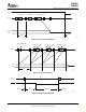
INTERFACE SEQUENCE
Power On, Attach, and Playback Sequence
PCM2901
PCM2903
SLES034C – MARCH 2002 – REVISED NOVEMBER 2007
The PCM2901/2903 requires a 12-MHz ( ± 500 ppm) clock for the USB and audio function, which can be
generated by a built-in crystal oscillator with a 12-MHz crystal resonator or supplied by an external clock. The
12-MHz crystal resonator must be connected to XTI (pin 21) and XTO (pin 20) with one high (1-M Ω ) resistor and
two small capacitors, the capacitance of which depends on the load capacitance of the crystal resonator. If the
external clock is used, the clock must be supplied to XTI, and XTO must be open.
The PCM2901/2903 has an internal power-on reset circuit, which works automatically when V
DD
(pin 27) exceeds
2.5 V typical (2.7 V to 2.2 V), and about 700 µ s is required until internal reset release.)
The PCM2903 employs both S/PDIF input and output. Isochronous-out data from the host is encoded to the
S/PDIF output and the DAC analog output. Input data is selected as either S/PDIF or ADC analog input. When
the device detects an S/PDIF input and successfully locks on the received data, the isochronous-in transfer data
source is automatically selected from S/PDIF itself; otherwise, the data source is selected to ADC analog input.
The following data formats are accepted by the S/PDIF input and output. All other data formats are unable to use
S/PDIF.
• 48-kHz 16-bit stereo
• 44.1-kHz 16-bit stereo
• 32-kHz 16-bit stereo
Mismatch between input data format and host command may cause unexpected results except in the following
conditions.
• Record monaural format from stereo data input at the same data rate
• Record 8-bit format from 16-bit data input at the same data rate
A combination of the foregoing conditions is not accepted.
For playback, all possible data-rate source is converted to 16-bit stereo format at the same source data rate.
The channel status information is fixed as consumer application, PCM mode, copyright, and digital/digital
converter. All other bits are fixed as 0s except for the sample frequency, which is set automatically according to
the data received through the USB.
Isochronous-in data is affected by the serial copy management system (SCMS). Where receiving digital audio
data that is indicated as original data in the control bit, input digital audio data transfers to the host. If the data is
indicated as first generation or higher, transferred data is selected to analog input.
Digital audio data output is always encoded as original with SCMS control.
The implementation of this feature is an option for the customer. Note that it is the user's responsibility whether
they implement this feature in their product or not.
The PCM2901/2903 is ready for setup when the reset sequence has finished and the USB bus is attached. In
order to perform certain reset sequences defined in the USB specification, V
DD
, V
CCC
, V
CCP1
, V
CCP2
, and V
CCX
must rise up with 10 ms / 3.3 V. After connection has been established by setup, the PCM2901/2903 is ready to
accept USB audio data. While waiting, the audio data (idle state) and analog output are set to bipolar zero (BPZ).
When receiving the audio data, the PCM2901/2903 stores the first audio packet, which contained 1-ms audio
data, into the internal storage buffer. The PCM2901/2903 starts playing the audio data when detecting the
following start of frame (SOF) packet.
24 Submit Documentation Feedback Copyright © 2002 – 2007, Texas Instruments Incorporated
Product Folder Link(s): PCM2901 PCM2903