
Datasheet


TypicalCircuitConnection2(ExampleofRemoteHeadphone)
VOLUME+
ExternalROM
(3)
(Optional)
SDA
V
BUS
D+
GND
SCL
USB ’B’
Connector
D–
C
8
R
1
SUSPEND
R
7
R
8
Headphone
31 30 29 28 27
FSEL
TEST
SSPND
XTI
XTO
CK
DT
PSEL
(2)
V
COM
AGNDR
V
CCR
V
OUT
R
(1)
V
OUT
L
(1)
V
CCL
AGNDL
ZGND
32 26
PGND
V
CCP
(3)
HOST
(2)
FUNC3
FUNC0
HID0/MS
HID1/MC
HID2/MD
PCM2706PJT
25
23
22
21
20
19
24
18
17
10 11 12 13 1491 5 16
2
3
4
5
6
1
7
8
V
BUS
D+
D–
V
DD
DGND
FUNC1
FUNC2
DOUT
C
5
+
C
6
C
3
C
4
X
1
C
1
C
2
R
11
+
C
9
+
C
10
R
9
R
10
C
11
R
5
C
12
R
6
C
7
R
2
R
3
R
4
PLAY/PAUSE
NEXT TRACK
MUTE
VOLUME–
PREVIOUSTRACK
STOP
PCM2704, ,PCM2705
PCM2706,PCM2707
www.ti.com
.......................................................................................................................................................SLES081F–JUNE2003–REVISEDJANUARY2009
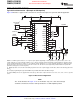
Figure33illustratesatypicalcircuitconnectionforabus-powered,100-mAheadphonewithsevenHIDs.
NOTE:X
1
:12-MHzcrystalresonator.C
1
,C
2
:10-pFto33-pFcapacitors(dependingonloadcapacitanceofcrystalresonator).C
3
-C
5
,C
7
,C
8
:
1-µFceramiccapacitors.C
6
:10-µFelectrolyticcapacitor.C
9
,C
10
:100-µFelectrolyticcapacitors(dependingonrequiredfrequencyresponse).
C
11
,C
12
:0.022-µFceramiccapacitors.R
1
:1MΩresistor.R
2
,R
11
:1.5kΩresistors.R
3
,R
4
:22Ωresistors.R
5
,R
6
:16Ωresistors.R
7
-R
10
:3.3
kΩresistors.
(1)OutputimpedanceofV
OUT
LandV
OUT
Rduringsuspendmodeorlackofpowersupplyis26kΩ±20%,whichisthedischargepathforC
9
andC
10
.
(2)DescriptorprogrammingthroughexternalROMisonlyavailablewhenPSELandHOSTarehigh.
(3)ExternalROMpowercanbesuppliedfromV
CCP
,butanyotheractivecomponentmustnotuseV
CCP
,V
CCL
,V
CCR
,orV
DD
asapower
source.
Figure33.Bus-PoweredApplication
NOTE:
ThecircuitillustratedinFigure33isforinformationonly.Theentireboarddesign
shouldbeconsideredtomeettheUSBspecificationasaUSB-compliantproduct.
Copyright©2003–2009,TexasInstrumentsIncorporatedSubmitDocumentationFeedback29
ProductFolderLink(s):PCM2704PCM2705PCM2706PCM2707
PCM2704 and PCM2705
Not Recommended For New Designs