
Datasheet


Table Of Contents
- FEATURES
- APPLICATIONS
- DESCRIPTION
- ORDERING INFORMATION
- ABSOLUTE MAXIMUM RATINGS
- RECOMMENDED OPERATING CONDITIONS
- ELECTRICAL CHARACTERISTICS
- THERMAL INFORMATION
- THERMAL INFORMATION
- DEVICE INFORMATION
- FUNCTIONAL BLOCK DIAGRAMS
- TYPICAL CHARACTERISTICS: INTERNAL FILTER
- TYPICAL CHARACTERISTICS: GENERAL
- DETAILED DESCRIPTION
- Clock and Reset
- Operation Mode Selection
- USB Interface
- DAC
- Digital Audio Interface: S/PDIF Output
- Digital Audio Interface: I2S Interface Output (PCM2706C/7C)
- DESCRIPTOR DATA MODIFICATION
- External ROM Descriptor (PCM2704C/6C)
- External ROM Example
- Serial Programming Interface (PCM2705C/7C)
- SPI Register (PCM2705C/7C)
- USB Host Interface Sequence
- EXAMPLE CIRCUITS
- Revision History
Ready for Setup
Ready for Playback
V
DD
0 V
D+ / D-
SSPND
V L
V R
OUT
OUT
2.0 V (typ)
Bus Idle
Bus Reset
Set Configuration
SOF
First Audio Data
SOF SOF
Second Audio Data
3.3 V (typ)
BPZ
1 ms
Device Setup
700 sm
Internal Reset
PCM2704C, PCM2705C
PCM2706C, PCM2707C
SBFS036A –AUGUST 2011–REVISED JULY 2012
www.ti.com
USB Host Interface Sequence
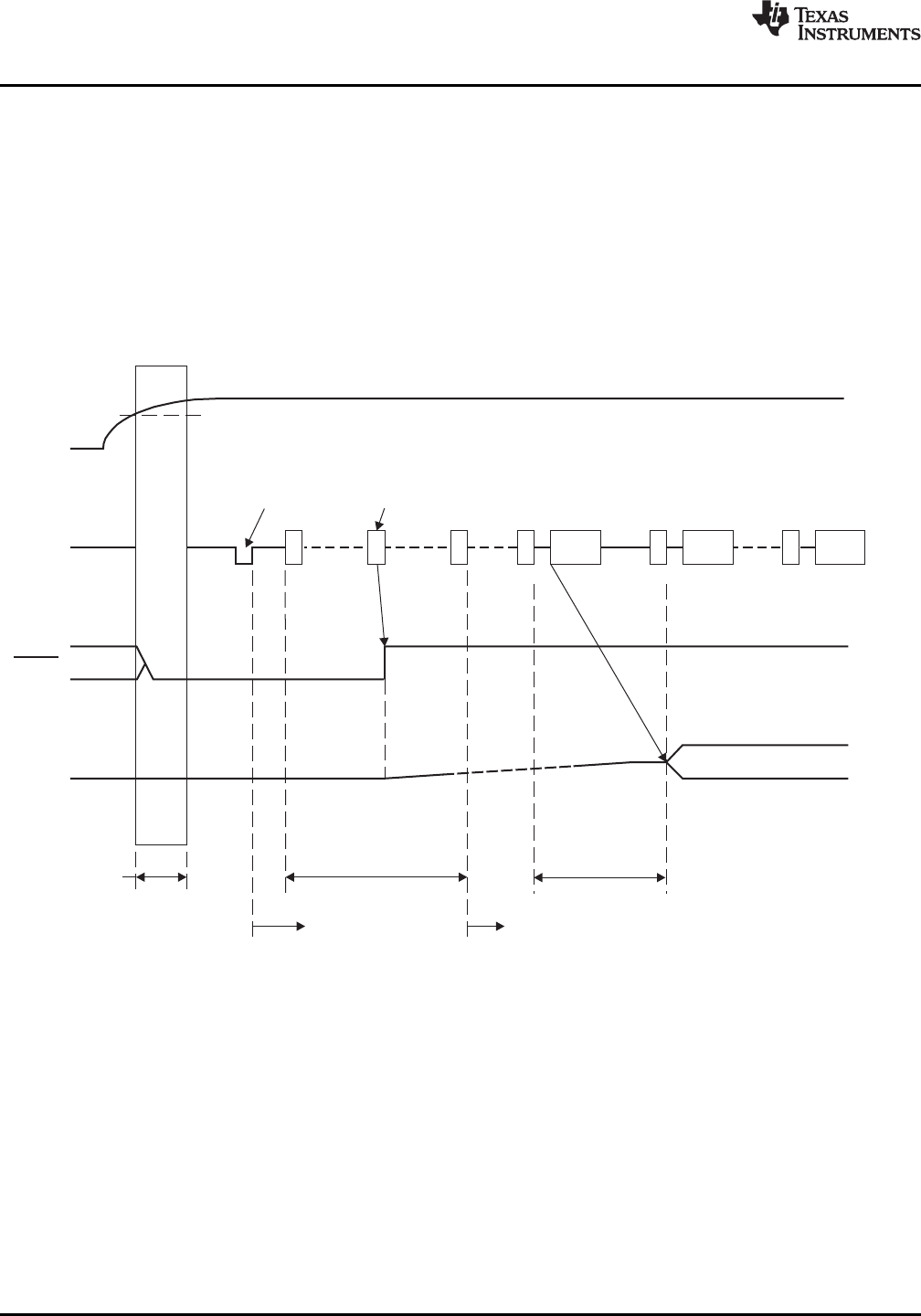
Power-On, Attach, and Playback Sequence
The PCM2704C/5C/6C/7C are ready for setup when the reset sequence has finished and the USB bus is
attached. After a connection has been established (through the set-up process), the PCM2704C/5C/6C/7C are
ready to accept USB audio data. While waiting for the audio data (that is, the device is in an idle state), the
analog output is set to bipolar zero (BPZ).
Upon receiving the audio data, the PCM2704C/5C/6C/7C stores the first audio packet into the internal storage
buffer. The packet contains 1 ms of audio data. The PCM2704C/5C/6C/7C start playing the audio data after
detecting the next subsequent start-of-frame (SOF) packet. Figure 31 shows the initial operation sequence for
the device.
Figure 31. Initial Sequence
28 Submit Documentation Feedback Copyright © 2011–2012, Texas Instruments Incorporated
Product Folder Link(s): PCM2704C PCM2705C PCM2706C PCM2707C