
Datasheet


Table Of Contents
- FEATURES
- APPLICATIONS
- DESCRIPTION
- ORDERING INFORMATION
- ABSOLUTE MAXIMUM RATINGS
- RECOMMENDED OPERATING CONDITIONS
- ELECTRICAL CHARACTERISTICS
- THERMAL INFORMATION
- THERMAL INFORMATION
- DEVICE INFORMATION
- FUNCTIONAL BLOCK DIAGRAMS
- TYPICAL CHARACTERISTICS: INTERNAL FILTER
- TYPICAL CHARACTERISTICS: GENERAL
- DETAILED DESCRIPTION
- Clock and Reset
- Operation Mode Selection
- USB Interface
- DAC
- Digital Audio Interface: S/PDIF Output
- Digital Audio Interface: I2S Interface Output (PCM2706C/7C)
- DESCRIPTOR DATA MODIFICATION
- External ROM Descriptor (PCM2704C/6C)
- External ROM Example
- Serial Programming Interface (PCM2705C/7C)
- SPI Register (PCM2705C/7C)
- USB Host Interface Sequence
- EXAMPLE CIRCUITS
- Revision History
1
1 1
1 1
1
2 2 2
2 2 2
3 3
3 3
14 14
14 14
15 15
15 15
16 16
16 16
SYSCK
(256 f )
S
LRCK
BCK
(64 f )
S
DOUT
DIN
MSB MSB MSBLSB LSB
L-Channel R-Channel
1/f
S
PCM2704C, PCM2705C
PCM2706C, PCM2707C
SBFS036A –AUGUST 2011–REVISED JULY 2012
www.ti.com
DAC
The PCM2704C/5C/6C/7C have a DAC that uses an oversampling technique with 128-f
S
, second-order, multi-bit
noise shaping. This technique provides extremely low quantization noise in the audio band, and the built-in
analog low-pass filter removes the high-frequency components of the noise-shaping signal. The DAC analog
outputs, V
OUT
L and V
OUT
R , are sent through the headphone amplifier and can provide 12 mW at 32 Ω as well as
1.8 V
PP
into a 10-kΩ load.
Digital Audio Interface: S/PDIF Output
The PCM2704C/5C/6C/7C employ S/PDIF output. Isochronous-out data from the host are encoded to S/PDIF
output DOUT, as well as to DAC analog outputs V
OUT
L and V
OUT
R. The interface format and timing follow the
IEC-60958 standard. Monaural data are converted to the stereo format at the same data rate. S/PDIF output is
not supported in the I
2
S I/F enable mode. The implementation of this feature is optional. Note that it is the
responsibility of the user to determine whether or not to implement this feature in the end application.
Channel Status Information
Channel status information is fixed, and includes consumer application, PCM mode, copyright, and digital/digital
converter data. All other bits are fixed as 0s, except for the sample frequency, which is set automatically
according to the data received through the USB.
Copyright Management
Digital audio data output always is encoded as original with SCMS control. Only one generation of digital
duplication is allowed.
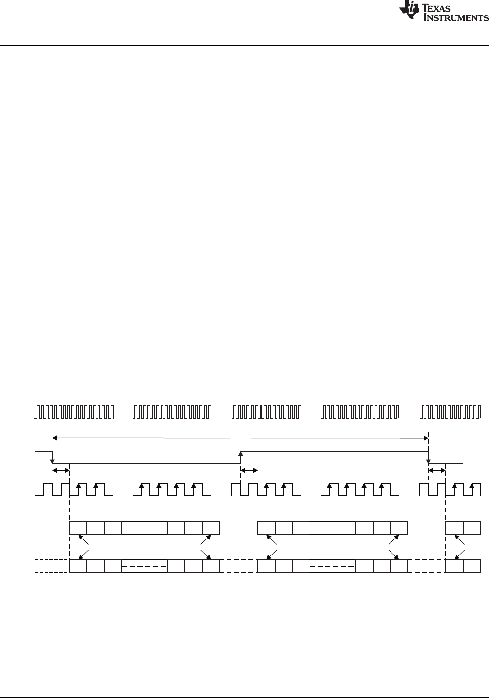
Digital Audio Interface: I
2
S Interface Output (PCM2706C/7C)
The PCM2706C and PCM2707C can support the I
2
S interface, which is enabled by the FSEL pin (pin 9). In the
I
2
S interface-enabled mode, pins 4, 18, 19, 5, and 17 are assigned as DIN, SYSCK, BCK, LRCK, and DOUT,
respectively. These pins provide digital output/input data in the 16-bit I
2
S format, which also is accepted by the
internal DAC. I
2
S interface format and timing are shown in Figure 24, Figure 25, and Figure 26. Table 9 and
Table 10 list the audio interface timing and audio clock timing characteristics, respectively.
Figure 24. Audio Data Interface Format
20 Submit Documentation Feedback Copyright © 2011–2012, Texas Instruments Incorporated
Product Folder Link(s): PCM2704C PCM2705C PCM2706C PCM2707C