
Datasheet


SLES071B − MARCH 2003 − REVISED NOVEMBER 2006
www.ti.com
35
Analog Gain of Balanced Amplifier
The DAC voltage outputs are followed by balanced amplifier stages, which sum the differential signals for each
channel, creating a single-ended voltage output. In addition, the balanced amplifiers provide a third-order
low-pass filter function, which band limits the audio output signal. The cutoff frequency and gain are determined
by external R and C component values. In this case, the cutoff frequency is 77 kHz with a gain of 1.83. The
output voltage for each channel is 5.9 Vp-p, or 2.1 V rms.
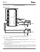
Application for Monaural-Mode Operation
A single-channel signal from the stereo audio data input is output from both V
OUT
L and V
OUT
R as a differential
output. The channel to be output is selected by setting the CHSL bit in register 20. The advantage of monaural
operation is to provide over 115 dB of dynamic range for high-end audio applications.
–
+
C
3
C
1
C
2
R
2
18
17
13
12
PCM1791A
V
OUT
R+
V
OUT
L–
V
OUT
L+
V
OUT
R–
R
4
R
1
R
3
R
5
R
6
R
8
R
7
L/R Clock
Bit Clock
System Clock
Audio Data
PCM1791A
PCM1791A
Controller
Analog
Output
Stage
V
OUT
R-Channel
Analog
Output
Stage
V
OUT
L-Channel
Analog Output Stage
NOTE
:
Example R and C values for f
C
= 77 kHz, R1–R4: 3.6 kΩ, R5, R6: 3.3 kΩ, R7, R8: 680 Ω, C1: 1800 pF, C2, C3: 560 pF.
Figure 37. Connection Diagram for Monaural Mode Interface