
Datasheet


R
L
= 1 kΩ
V
CC
C
L
= 50 pF
(see Note A)
t
buf
t
icr
t
sth
t
sds
t
sdh
t
icf
t
icr
t
scl
t
sch
t
sts
t
PHL
t
PLH
0.3 × V
CC
Stop
Condition
t
sps
Repeat
Start
Condition
Start or
Repeat
Start
Condition
SCL
SDA
Start
Condition
(S)
Address
Bit 7
(MSB)
Data
Bit 0
(LSB)
Stop
Condition
(P)
Three Bytes for Complete
Device Programming
SDA LOAD CONFIGURATION
VOLTAGE WAVEFORMS
t
icf
Stop
Condition
(P)
t
sp
DUT
SDA
0.7 × V
CC
0.3 × V
CC
0.7 × V
CC
R/W
Bit 0
(LSB)
ACK
(A)
Data
Bit 7
(MSB)
Address
Bit 1
Address
Bit 6
BYTE DESCRIPTION
1 I
2
C address
2, 3 P-port data
PCA9539
SCPS130F –AUGUST 2005–REVISED JANUARY 2011
www.ti.com
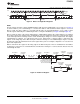
PARAMETER MEASUREMENT INFORMATION
A. C
L
includes probe and jig capacitance.
B. All inputs are supplied by generators having the following characteristics: PRR ≤ 10 MHz, Z
O
= 50 Ω, t
r
/t
f
≤ 30 ns.
C. All parameters and waveforms are not applicable to all devices.
Figure 11. I
2
C Interface Load Circuit and Voltage Waveforms
18 Submit Documentation Feedback Copyright © 2005–2011, Texas Instruments Incorporated
Product Folder Link(s): PCA9539