
Datasheet


LED
LEDx
V
CC
100 kW
V
CC
LED
3.3 V
5 V
LEDx
V
CC
V
CC
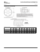
Ramp-Up Re-Ramp-Up
Time to Re-Ramp
Time
Ramp-Down
V
CC_RT
V
CC_RT
V
CC_FT
V
CC_TRR_GND
PCA9534
www.ti.com
SCPS124G –SEPTEMBER 2006–REVISED JUNE 2010
Minimizing I
CC
When the I/O Controls LEDs
When the I/Os are used to control LEDs, they are normally connected to V
CC
through a resistor, as shown in
Figure 14. Because the LED acts as a diode, when the LED is off, the I/O V
IN
is about 1.2 V less than V
CC
. The
supply current, I
CC
, increases as V
IN
becomes lower than V
CC
and is specified as ΔI
CC
in Electrical
Characteristics.
For battery-powered applications, it is essential that the voltage of the I/O pins is greater than or equal to V
CC
when the LED is off to minimize current consumption. Figure 15 shows a high-value resistor in parallel with the
LED. Figure 16 shows V
CC
less than the LED supply voltage by at least 1.2 V. Both of these methods maintain
the I/O V
IN
at or above V
CC
and prevents additional supply-current consumption when the LED is off.
Figure 15. High-Value Resistor in Parallel With the LED
Figure 16. Device Supplied by a Lower Voltage
Power-On Reset Requirements
In the event of a glitch or data corruption, PCA9534 can be reset to its default conditions by using the power-on
reset feature. Power-on reset requires that the device go through a power cycle to be completely reset. This
reset also happens when the device is powered on for the first time in an application.
The two types of power-on reset are shown in Figure 17 and Figure 18.
Figure 17. V
CC
is Lowered Below 0.2 V or 0 V and Then Ramped Up to V
CC
Copyright © 2006–2010, Texas Instruments Incorporated Submit Documentation Feedback 23
Product Folder Link(s): PCA9534