
Datasheet


www.ti.com
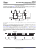
PARAMETER MEASUREMENT INFORMATION
20%
t
PLZ
/t
PZL
V
CC
TEST S1
C
L
= 50 pF
(see Note B)
S1
GND
R
L
= 1.35 kΩ
V
CC
Output
PULSE
GENERATOR
DUT
R
T
(see Note A)
V
CC
V
IN
V
OUT
V
OL
t
tHL
t
tLH
V
CC
t
PLZ
t
PZL
1.5 V 1.5 V
V
CC
0 V
Input
1.5 V 1.5 V
20%
80% 80%
VOLTAGE WAVEFORMS
PROPAGATION DELAY AND OUTPUT TRANSITION TIMES
TEST CIRCUIT FOR OPEN-DRAIN OUTPUT
PCA9515A
DUAL BIDIRECTIONAL I
2
C BUS AND SMBus REPEATER
SCPS150B – DECEMBER 2005 – REVISED OCTOBER 2007
A. R
T
termination resistance should be equal to Z
OUT
of pulse generators.
B. C
L
includes probe and jig capacitance.
C. All input pulses are supplied by generators having the following characteristics: PRR ≤ 10 MHz, Z
O
= 50 Ω ,
slew rate ≥ 1 V/ns.
D. The outputs are measured one at a time, with one transition per measurement.
E. t
PLH
and t
PHL
are the same as t
pd
.
F. t
PLZ
and t
PHZ
are the same as t
dis
.
G. t
PZL
and t
PZH
are the same as t
en
.
Figure 1. Test Circuit and Voltage Waveforms
6 Submit Documentation Feedback Copyright © 2005 – 2007, Texas Instruments Incorporated
Product Folder Link(s): PCA9515A