
Datasheet


www.ti.com
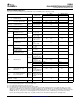
P82B96
Sx (SDA)
Sy (SCL)
Ry (RxD, SCL)
Ty (TxD, SCL)
Rx (RxD, SDA)
Tx (TxD, SDA)
1
7
4
GND
6
5
2
3
8
V (2–15V)
CC
Functional Description
Sx and Sy
Tx and Ty
P82B96
DUAL BIDIRECTIONAL BUS BUFFER
SCPS144B – MAY 2006 – REVISED JULY 2007
FUNCTIONAL BLOCK DIAGRAM
The I
2
C pins, Sx and Sy, are designed to interface with a normal I
2
C bus. The logic threshold-voltage levels on
the I
2
C bus are independent of the supply V
CC
. The maximum I
2
C bus supply voltage is 15 V, and the specified
static sink current is 3 mA.
Sx and Sy have two identical buffers. Each buffer is made up of two logic signal paths. The first one, named Tx
or Ty, is a forward path from the I
2
C interface pin, which drives the buffered bus. The second one, named Rx or
Ry, is a reverse signal path from the buffered bus input to drive the I
2
C bus interface.
There are two purposes for these paths: to sense the voltage state of the I
2
C pin (Sx or Sy) and transmit this
state to Tx or Ty, respectively, and to detect the state of the Rx or Ry and pull the I
2
C pin low when Rx or Ry is
low.
Tx and Ty are open-collector outputs without ESD protection diodes to V
CC
. Each pin may be connected via a
pullup resistor to a supply voltage in excess of V
CC
, as long as the 15-V rating is not exceeded. Tx and Ty have
a larger current-sinking capability than a normal I
2
C device and can sink a static current of greater than 30 mA.
They also have dynamic pulldown capability of 100-mA, typically.
A logic low is transmitted to Tx or Ty only when the voltage at the I
2
C pin (Sx or Sy) is below 0.6 V. A logic low
at Rx or Ry causes the I
2
C bus (Sx or Sy) to be pulled to a logic low level in accordance with I
2
C requirements
(maximum 1.5 V in 5-V applications), but not low enough to be looped back to the Tx or Ty output and cause the
buffer to latch low.
The minimum low level that the P82B96 can achieve on the I
2
C bus by a low at Rx or Ry typically is 0.8 V.
If V
CC
fails, neither the I
2
C pins nor the Tx or Ty outputs are held low. Their open-collector configuration allows
them to be pulled up to the rated maximum of 15 V without V
CC
present. The input configuration on Sx, Sy, Rx,
and Ry also presents no loading of external signals when V
CC
is not present.
The effective input capacitance of any signal pin, measured by its effect on bus rise times, is less than 4 pF for
all bus voltages and supply voltages, including V
CC
= 0 V.
3
Submit Documentation Feedback