
Datasheet


OPA835
OPA835
OPA835
V
IN-
V
IN+
V
SIG-
V
SIG+
V
CM
V
CM
R
G1
R
F1
R
F1
R
G2
R
G2
R
F2
R
F2
V
OUT
G[(V )-(
SIG
+
V )]
SIG-
V
REF
V
REF
æ ö æ ö
ç ÷ ç ÷
è ø è ø
F1 F2
G 1 G2
2R R
G = 1 +
R R
( )
F1 F2
IN+ IN REF
G1 G2
2R R
V = V V 1 + + V
OUT
R R
-
æ ö æ ö
- ´
ç ÷ ç ÷
è ø è ø
OPA 835
OPA 835
GV
SIG-
V
IN-
V
SIG-
V
SIG+
V
CM
V
CM
R
G
R
F
R
F
V
IN+
V
OUT-
V
OUT+
V
CM
V
CM
GV
SIG+
F
G
2R
G = 1 +
R
±
æ ö
´
ç ÷
±
è ø
F
IN CM
G
2R
V = V 1 + + V
OUT
R
OPA835
OPA2835
SLOS713E –JANUARY 2011–REVISED JULY 2013
www.ti.com
(5)
The signal gain of the circuit is set by: , and V
CM
passes with unity gain. The amplifier in essence
combines two non-inverting amplifiers into one differential amplifier with the R
G
resistor shared, which makes R
G
effectively ½ its value when calculating the gain. The output signals are in-phase with the input signals.
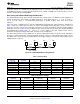
Figure 58. Differential to Differential Amplifier
Instrumentation Amplifier
Figure 59 is an instrumentation amplifier that combines the high input impedance of the differential to differential
amplifier circuit and the common-mode rejection of the differential to single-ended amplifier circuit. This circuit is
often used in applications where high input impedance is required like taps from a differential line or in cases
where the signal source is a high impedance.
If we set V
IN+
= V
CM
+ V
SIG+
and V
IN-
= V
CM
+ V
SIG-
, then
(6)
The signal gain of the circuit is set by:
, V
CM
is rejected, and V
REF
provides a level shift around which the output signal
swings. The single ended output signal is in-phase with the differential input signal.
Figure 59. Instrumentation Amplifier
26 Submit Documentation Feedback Copyright © 2011–2013, Texas Instruments Incorporated
Product Folder Links: OPA835 OPA2835