
Datasheet


www.ti.com
Video Line Driver
1/2
OPA2652
V
OUT
V
IN
+5V
-5V
C
2
C
1
402W
402W
402W
Video
Output
Video
Input
1/2
OPA2652
402W402W
+5V
-5V
75.0W
75.0W
DESIGN-IN TOOLS
Demonstration Fixtures
Pulse Delay Circuit
Macromodels and Applications Support
1/2
OPA2652
1/2
OPA2652
402W
C
R
402W
R
G
402W
R
F
402W
C
V
O
V
IN
+5V
-5V
+5V
-5V
R
Simple Bandpass Filter
OPA2652
SBOS125A – JUNE 2000 – REVISED MAY 2006
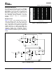
Figure 32 shows the OPA2652 used as a video line
driver. Its outstanding differential gain and phase
allow it to be used in studio equipment, while its low
cost and SOT23-8 package option also support
consumer applications.
Figure 34. Inverting Bandpass Filter
Figure 32. Video Line Driver
Two printed circuit boards (PCBs) are available to
assist in the initial evaluation of circuit performance
Figure 33 shows the OPA2652 used in a pulse delay
using the OPA2652 in its two package options. Both
circuit. This circuit cascades the two op amps in the
of these are offered free of charge as unpopulated
OPA2652, each forming a single pole, active allpass
PCBs, delivered with a user's guide. The summary
filter. The overall gain is +1, and the overall delay
information for these fixtures is shown in Table 1 .
through the filter is:
Table 1. Demonstration Fixtures for the OPA2652
t
GD
= n(2RC), overall group delay
ORDERING LITERATURE
n = 2, the number of cascaded stages
PRODUCT PACKAGE NUMBER NUMBER
OPA2652U SO-8 DEM-OPA-SO-2A SBOU003
OPA2652E SOT23-8 DEM-OPA-SOT-2A SBOU001
The demonstration fixtures can be requested at the
Texas Instruments web site (www.ti.com ) through the
OPA2652 product folder.
Computer simulation of circuit performance using
SPICE is often useful when analyzing the
Figure 33. Pulse Delay Circuit
performance of analog circuits and systems. This
method is particularly true for video and RF amplifier
circuits where parasitic capacitance and inductance
R
F
and R
G
need to be equal to maintain a constant
can have a major effect on circuit performance.
gain magnitude. The rise and fall times of the input
Check the Texas Instruments web site (www.ti.com )
pulses, tr
(IN)
, should be slow enough to prevent
for available SPICE products (note that not all parts
pre-shoot artifacts in the response.
have models). These models do a good job of
tr
(IN)
≥ 5RC, minimal pre-shoot
predicting small-signal AC and transient performance
under a wide variety of operating conditions. They do
not do as well in predicting the harmonic distortion or
dG/d φ characteristics. These models do not attempt
Figure 34 shows the OPA2652 used as simple
to distinguish between the package types in
bandpass filter. The OPA2652 is well-suited for this
small-signal AC performance.
type of circuit because it is very stable at a noise
gain of +1.
12
Submit Documentation Feedback