
Datasheet


www.ti.com
Pulse-Position Modulation
Voltage − 2 V/div
R
A
= 3 kΩ
R
B
= 500 Ω
R
L
= 1 kΩ
See Figure 20
Capacitor Voltage
Output Voltage
Modulation Input Voltage
Time − 0.1 ms/div
R
B
Modulation
Input
(see Note A)
CONT
TRIG
RESET V
CC
OUT
DISCH
V
CC
(5 V to 15 V)
R
L
R
A
C
GND
THRES
NOTE A: The modulating signal can be direct or capacitively coupled
to CONT. For direct coupling, the effects of modulation
source voltage and impedance on the bias of the timer
should be considered.
Pin numbers shown are for the D, JG, P, PS, and PW packages.
4 8
3
7
6
2
5
Output
NA555 , NE555 , SA555 , SE555
PRECISION TIMERS
SLFS022F – SEPTEMBER 1973 – REVISED JUNE 2006
APPLICATION INFORMATION (continued)
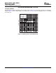
As shown in Figure 20 , any of these timers can be used as a pulse-position modulator. This application
modulates the threshold voltage and, thereby, the time delay, of a free-running oscillator. Figure 21 shows a
triangular-wave modulation signal for such a circuit; however, any wave shape could be used.
Figure 20. Circuit for Pulse-Position Modulation Figure 21. Pulse-Position-Modulation Waveforms
14
Submit Documentation Feedback