
Datasheet


MSP430F673x
MSP430F672x
SLAS731C –DECEMBER 2011–REVISED FEBRUARY 2013
www.ti.com
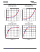
Crystal Oscillator, XT1, Low-Frequency Mode
(1)
(continued)
over recommended ranges of supply voltage and operating free-air temperature (unless otherwise noted)
PARAMETER TEST CONDITIONS V
CC
MIN TYP MAX UNIT
XTS = 0, Measured at ACLK,
Duty cycle LF mode 30 70 %
f
XT1,LF
= 32768 Hz
Oscillator fault frequency,
f
Fault,LF
XTS = 0
(8)
10 10000 Hz
LF mode
(7)
f
OSC
= 32768 Hz, XTS = 0, XT1BYPASS = 0,
1000
XT1DRIVEx = 0, T
A
= 25°C, C
L,eff
= 6 pF
t
START,LF
Startup time, LF mode 3.0 V ms
f
OSC
= 32768 Hz, XTS = 0, XT1BYPASS = 0,
500
XT1DRIVEx = 3, T
A
= 25°C, C
L,eff
= 12 pF
(7) Frequencies below the MIN specification set the fault flag. Frequencies above the MAX specification do not set the fault flag.
Frequencies in between might set the flag.
(8) Measured with logic-level input frequency but also applies to operation with crystals.
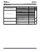
Internal Very-Low-Power Low-Frequency Oscillator (VLO)
over recommended ranges of supply voltage and operating free-air temperature (unless otherwise noted)
PARAMETER TEST CONDITIONS V
CC
MIN TYP MAX UNIT
f
VLO
VLO frequency Measured at ACLK 1.8 V to 3.6 V 6 9.4 15 kHz
df
VLO
/d
T
VLO frequency temperature drift Measured at ACLK
(1)
1.8 V to 3.6 V 0.5 %/°C
df
VLO
/dV
CC
VLO frequency supply voltage drift Measured at ACLK
(2)
1.8 V to 3.6 V 4 %/V
Duty cycle Measured at ACLK 1.8 V to 3.6 V 30 70 %
(1) Calculated using the box method: (MAX(-40 to 85°C) – MIN(-40 to 85°C)) / MIN(85°C – (–40°C))
(2) Calculated using the box method: (MAX(1.8 to 3.6 V) – MIN(1.8 to 3.6 V)) / MIN(1.8 to 3.6 V) / (3.6 V – 1.8 V)
Internal Reference, Low-Frequency Oscillator (REFO)
over recommended ranges of supply voltage and operating free-air temperature (unless otherwise noted)
PARAMETER TEST CONDITIONS V
CC
MIN TYP MAX UNIT
REFO oscillator current
I
REFO
T
A
= 25°C 1.8 V to 3.6 V 3 µA
consumption
REFO frequency calibrated Measured at ACLK 1.8 V to 3.6 V 32768 Hz
f
REFO
Full temperature range 1.8 V to 3.6 V ±3.5 %
REFO absolute tolerance calibrated
T
A
= 25°C 3 V ±1.5 %
df
REFO
/d
T
REFO frequency temperature drift Measured at ACLK
(1)
1.8 V to 3.6 V 0.01 %/°C
df
REFO
/dV
CC
REFO frequency supply voltage drift Measured at ACLK
(2)
1.8 V to 3.6 V 1.0 %/V
Duty cycle Measured at ACLK 1.8 V to 3.6 V 40 50 60 %
t
START
REFO startup time 40%/60% duty cycle 1.8 V to 3.6 V 25 µs
(1) Calculated using the box method: (MAX(-40 to 85°C) – MIN(-40 to 85°C)) / MIN(85°C – (–40°C))
(2) Calculated using the box method: (MAX(1.8 to 3.6 V) – MIN(1.8 to 3.6 V)) / MIN(1.8 to 3.6 V) / (3.6 V – 1.8 V)
56 Submit Documentation Feedback Copyright © 2011–2013, Texas Instruments Incorporated