
Datasheet


2.01.8
8
0
12
20
25
SystemFrequency-MHz
SupplyVoltage-V
ThenumberswithinthefieldsdenotethesupportedPMMCOREVxsettings.
2.2 2.4 3.6
0,1,2,30,1,20,10
1,2,3
1,2
1
2,3
3
2
MSP430F5510, MSP430F5509, MSP430F5508, MSP430F5507
MSP430F5506, MSP430F5505, MSP430F5504, MSP430F5503
MSP430F5502, MSP430F5501, MSP430F5500
www.ti.com
SLAS645I –JULY 2009–REVISED NOVEMBER 2013
Figure 2. Maximum System Frequency
Electrical Characteristics
Active Mode Supply Current Into V
CC
Excluding External Current
over recommended operating free-air temperature (unless otherwise noted)
(1) (2) (3)
FREQUENCY (f
DCO
= f
MCLK
= f
SMCLK
)
EXECUTION
PARAMETER V
CC
PMMCOREVx 1 MHz 8 MHz 12 MHz 20 MHz 25 MHz UNIT
MEMORY
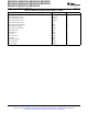
TYP MAX TYP MAX TYP MAX TYP MAX TYP MAX
0 0.25 0.27 1.55 1.68
1 0.28 1.74 2.58 2.78
I
AM, Flash
Flash 3 V mA
2 0.30 1.91 2.84 4.68 5.06
3 0.32 2.09 3.10 5.13 6.0 6.5
0 0.17 0.19 0.91 1.00
1 0.19 1.03 1.54 1.67
I
AM, RAM
RAM 3 V mA
2 0.20 1.16 1.73 2.84 3.11
3 0.21 1.24 1.87 3.1 3.9 4.3
(1) All inputs are tied to 0 V or to V
CC
. Outputs do not source or sink any current.
(2) The currents are characterized with a Micro Crystal MS1V-T1K crystal with a load capacitance of 12.5 pF. The internal and external load
capacitance are chosen to closely match the required 12.5 pF.
(3) Characterized with program executing typical data processing. USB disabled (VUSBEN = 0, SLDOEN = 0).
f
ACLK
= 32786 Hz, f
DCO
= f
MCLK
= f
SMCLK
at specified frequency.
XTS = CPUOFF = SCG0 = SCG1 = OSCOFF = SMCLKOFF = 0.
Copyright © 2009–2013, Texas Instruments Incorporated Submit Documentation Feedback 49
Product Folder Links: MSP430F5510 MSP430F5509 MSP430F5508 MSP430F5507 MSP430F5506 MSP430F5505
MSP430F5504 MSP430F5503 MSP430F5502 MSP430F5501 MSP430F5500